International Journal of Agricultural Science and Food Technology
Applications of IoT in Agricultural System
Ajit Kumar Singh*
Cite this as
Singh AK (2020) Applications of IoT in Agricultural System. Int J Agric Sc Food Technol 6(1): 041-045. DOI: 10.17352/2455-815X.000053Agriculture in India is the means of livelihood of almost two thirds of the work force in the country. It has always been India’s most important economic sector. The increase in post independence agricultural production has been brought about by bringing additional area under cultivation, extension of irrigation facilities, use of better seeds, better techniques, water management and plant protection. The life of a farmer goes beyond tilling and yielding crops. The farmer should be alert to water the fields at regular intervals of time to obtain good results . To protect the field from drying due to lack of sufficient water and informing the owner of the field about the weather conditions in the field. To measure the different weather parameters in the field and soil moisture level in the field. It provides an easy and efficient technique to water the fields whenever the moisture level in the soil drops down. This system is entirely an automated one. The set up consists of ARDUINO UNO microcontroller, sensors as an important part as they are responsible for controlling the irrigation on field. ATMEGA 328P is an advanced version of microcontroller and forms the heart of the system. To measure different climate parameters, we are using different sensors like temperature, humidity sensors etc. To detect the rain fall and the humidity in the weather we are using the rain detect sensor and the humidity sensor respectively. All of the measured sensor parameters are sent to the predefined web server by using the Wi-Fi module. To this Wi-Fi module, we should provide the internet to that by using the mobile hot spot. And if any of the sensor activates, then the corresponding alert message will also send to the concerned person via SMS using the GSM module.
Introduction
As an important form of modern agriculture, greenhouse cultivation has been paid more and more attention. The main characteristics of modern greenhouse are to introduce sensor technology, embedded technology, wired and wireless communication technology in the design of greenhouse environment monitoring and control system. Rehmana, et al. (2015) and Chaudhary, et al. (2011) reported. Greenhouse environmental monitoring is to obtain the most suitable growth and development environment by changing the internal environment factors (temperature, humidity, light intensity, etc.) [1,2]. Early monitoring system of greenhouse environment monitoring system is mainly based on the local computer, and the monitoring terminal is based on the local computer, and the other part of the greenhouse environment monitoring is carried out by the wireless way, including the short distance Bluetooth, Zigbee network and GPRS network communication. Raul Lionel and et al. (2012) reported. This paper describes in Wi-Fi according to different greenhouse crops to develop suitable soil moisture, soil temperature concentration and light strength parameters, and set the appropriate threshold to send alarm information to the mobile terminal, according to the actual requirement of the automatic water supply, ventilation, lighting and other operations. Meloa and et al. (2014) reported [2,3]. Users can monitor the information management of the greenhouse monitoring information management applications to smart phones, tablet PCs and other mobile terminal equipment. In addition, users can give full play to the mobile characteristics of the terminal, to monitor the greenhouse crop growth at real time, and to develop the corresponding crop growth plan, and truly achieve the information of agricultural production [2,4].
To improve efficiency, productivity, global market and to reduce human intervention, time and cost there is a need to divert towards new technology named Internet of Things. IoT is the network of devices to transfer the information without human involvement. Hence, to gain high productivity, IoT works in synergy with agriculture to obtain smart farming. This paper focuses on role of IoT in agriculture that leads to smart framing.
Exsisting system
In the existing system, there is no source of informing the farmer about the condition of his paddy field via SMS. If any of the sensors goes beyond the set limit or any problem occurs to the motor he can only know by opening the web server. To avoid this situation, we are developing the proposed system, in which the farmer can know immediately if any of the sensors goes beyond the threshold level by SMS.
Proposed system
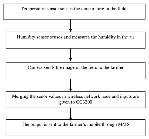
In the proposed system, we are using different sensors like temperature, humidity, soil moisture, rain fall sensors in our project. All of the sensors are interfaced to the ADC channels of the controller and displaying those digital values on the LCD screen and sending those values to the web server by using the Wi-Fi module. The farmer can login into this web server, and view the conditions of the field remotely [5]. The motor will on automatically and supply water to the field if the moisture level is below the set threshold limit. And if any of the sensor activates, then the corresponding alert message will also send to the concerned person via SMS using the GSM module. By this way, if the net connection is not available, with the help of the alert SMS, the farmer can know the particular sensor values if it goes beyond threshold limit Figures 1,2.
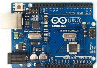
Hardware implementation A. arduino smd
The ATmega328/P provides the following features: 32Kbytes of In-System Programmable Flash with Read-While-Write capabilities, 1Kbytes EEPROM, 2Kbytes SRAM, 23 general purpose I/O lines, 32 general purpose working registers, Real Time Counter (RTC), three flexible Timer/Counters with compare modes and PWM, 1 serial programmable USARTs , 1 byte-oriented 2-wire Serial Interface (I2C), a 6-channel 10-bit ADC (8 channels in TQFP and QFN/MLF packages), a programmable Watchdog Timer with internal Oscillator, an SPI serial port, and six software selectable power saving modes. The Idle mode stops the CPU while allowing the SRAM, Timer/Counters, SPI port, and interrupt system to continue functioning. The Power-down mode saves the register contents but freezes the Oscillator, disabling all other chip functions until the next interrupt or hardware reset. In Power-save mode, the asynchronous timer continues to run, allowing the user to maintain a timer base while the rest of the device is sleeping [6]. The ADC Noise Reduction mode stops the CPU and all I/O modules except asynchronous timer and ADC to minimize switching noise during ADC conversions. In Standby mode, the crystal/resonator oscillator is running while the rest of the device is sleeping. This allows very fast start-up combined with low power consumption. In Extended Standby mode, both the main oscillator and the asynchronous timer continue to run [6].
WI-FI
Wi-Fi, also spelled Wi-Fi or Wi-Fi, is a local area wireless technology that allows an electronic device to exchange data or connect to the internet using 2.4 GHz UHF and 5 GHz SHF radio waves. The name is a trademark name, and is a play on the audiophile term Hi-Fi [7]. The Wi-Fi Alliance defines Wi-Fi as any “Wireless Local Area Network (WLAN) products that are based on the Institute of Electrical and Electronics Engineers’ (IEEE) standards” [7].
However, since most modern WLANs are based on these standards, the term “Wi-Fi” is used in general English as a synonym for “WLAN”. Only Wi-Fi products that complete Wi-Fi Alliance interoperability certification testing successfully may use the “Wi-Fi CERTIFIED” trademark. Many devices can use Wi-Fi, e.g., personal computers, video-game consoles, smart phones, some digital cameras, tablet computers and digital audio players [7].
These can connect to a network resource such as the Internet via a wireless network access point. Such an access point (or hotspot) has a range of about 20 meters (66 feet) indoors and a greater range outdoors. Hotspot coverage can comprise an area as small as a single room with walls that block radio waves, or as large as many square kilometers achieved by using multiple overlapping access points. Wi-Fi can be less secure than wired connections (such as Ethernet) because an intruder does not need a physical connection. Web pages that use SSL are secure but unencrypted internet access can easily be detected by intruders. Because of this, Wi-Fi has adopted various encryption technologies [8]. The early encryption WEP, proved easy to break. Higher quality protocols (WPA, WPA2) were added later. An optional feature added in 2007, called Wi-Fi Protected Setup (WPS), and had a serious flaw that allowed an attacker to recover the router’s password [7].
Software requirements
A. Arduino compiler: You also need a standard USB cable (A plug to B plug): the kind you would connect to a USB printer, for example. (For the Arduino Nano, you’ll need an A to Mini-B cable instead) [9].
The Arduino Uno, Mega, Duemilanove and Arduino Nano automatically draw power from either the USB connection to the computer or an external power supply. If you’re using an Arduino Diecimila, you’ll need to make sure that the board is configured to draw power from the USB connection. The power source is selected with a jumper, a small piece of plastic that fits onto two of the three pins between the USB and power jacks. Check that it’s on the two pins closest to the USB port. Connect the Arduino board to your computer using the USB cable. The green power LED (labeled PWR) should go on [10].
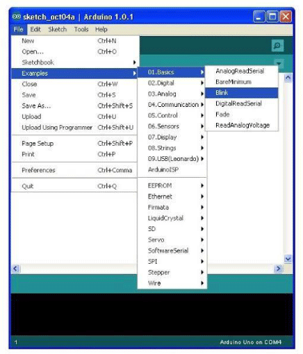
Open the blink example
Open the LED blink example sketch: File > Examples > 1.Basics > Blink (Figure 3).
B. Select your serial port: Select the serial device of the Arduino board from the Tools | Serial Port menu. This is likely to be COM3 or higher (COM1and COM2 are usually reserved for hardware serial ports). To find out, you can disconnect your Arduino board and re-open the menu; the entry that disappears should be the Arduino board. Reconnect the board and select that serial port [11,12].
C. Upload the program: Before uploading your sketch, you need to select the correct items from the Tools > Board and Tools > Serial Port menus. The boards are described below. On the Mac, the serial port is probably something like /dev/tty.usbmodem241 On Windows, it’s probably COM1 or COM2 (for a serial board) or COM4, COM5, COM7, or higher (for a USB board) - to find out, you look for USB serial device in the ports section of the Windows Device Manager. On Linux, it should be /dev/ttyUSB0,/dev/ttyUSB1 or similar [12,13].
Once you’ve selected the correct serial port and board, press the upload button in the toolbar or select the Upload item from the File menu. Current Arduino boards will reset automatically and begin the upload. With older boards (pre-Diecimila) that lack auto-reset, you’ll need to press the reset button on the board just before starting the upload. On most boards, you’ll see the RX and TX LEDs blink as the sketch is uploaded. The Arduino environment will display a message when the upload is complete, or show an error [12].
When you upload a sketch, you’re using the Arduino bootloader, a small program that has been loaded on to the microcontroller on your board. It allows you to upload code without using any additional hardware. The bootloader is active for a few seconds when the board resets; then it starts whichever sketch was most recently uploaded to the microcontroller. The bootloader will blink the onboard (pin 13) LED when it starts (i.e. when the board resets) [12].
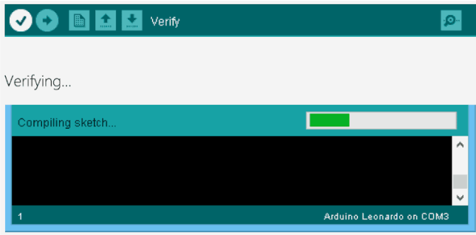
Now, simply click the “Upload” button in the environment. Wait a few seconds - you should see the RX and TX leds on the board flashing. If the upload is successful, the message “Done uploading.” will appear in the status bar. (Note: If you have an Arduino Mini, NG, or other board, you’ll need to physically present the reset button on the board immediately before pressing the upload button (Figure 4) [9].
Results
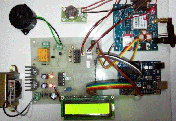
The Internet of things (IoT) is the most efficient and important techniques for development of solutions to the problems. IoT evolve from different building blocks which includes lots of sensors, software’s, network components and other electronic devices. Also it makes data more effective. IoT allows to exchange the data over the network without human human involvement Figures 5.
Assemble the circuit on the PCB as shown in circuit diagram. After assembling the circuit on the PCB, check it for proper connections before switching on the power supply [14]. Various test was carried out before, during and after the construction has been completed. The multi-meter was extensively used for carrying out most of these tests. Each subunit was tested and confirmed efficient. After the construction of the entire system, the program was written and burned into the microcontroller chip [15].
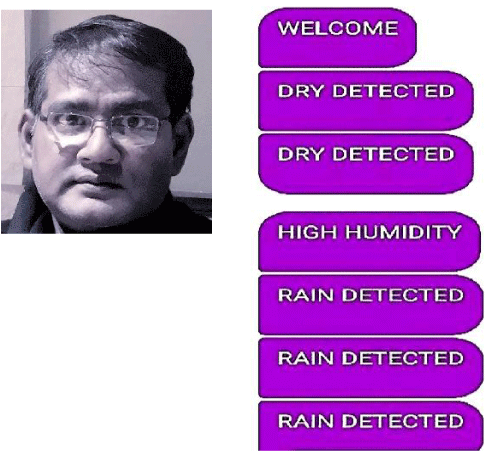
The yield appeared beneath signifies the temperature, soil dampness state and the gate crasher discovery. The nextoutcome is the yield as of the Android purpose that is produced in the cell phone. It decides the temperature, stickiness, dampness as well as the interloper discovery. The yield appeared beneath means the temperature, soil dampness state with the gate crasher identification. The second outcome is the yield from the Android purpose that is produced in the cell phone. It decides the temperature, dampness, dampness with the gate crasher location.
Conclusion
In this project a design and implementation of Arduino Based Agricultural System has been proposed. This system is able to collect the information about the main environmental parameters such as; Temperature, Humidity, pH inside the greenhouse.Integrating features of all the hardware components used have been developed in it. Presence of every module has been reasoned out and placed carefully, thus contributing to the best working of the unit. This project presents us with a chance to use maximum solar energy for power generation instead of going with nonrenewable energy resources and hence thus contributing a greenerenvironment.
The whole system is advanced, reliable and convenient. This design improves the real-time performance of the user to the agricultural environment change, and is conducive to the realization of the unattended goal, and promotes the development of the intelligent greenhouse. In future, this scheme can be used as a part of the development of remote monitoring of the Internet of things and can be applied on other areas of modern facilities agriculture .
Author
Ajit Singh is a teaching professional of Computer Science as well as an author. He has being teaching professionally for nearly 20 years, having begun his career at Patna University, India. He is particularly interested in writing academic research papers in the field of Computer Science.
- Prathyusha K, S Chaitanya (2012) Design of Embedded System for the Automation of Drip Irrigation. IJAIEM 2012.
- AIDIC. Link: https://bit.ly/3gdqiLs
- Akyildig IF, Su W, Sankarasubramaniam Y, Cayirci E (2002) A Survey on Sensor Networks. IEEE Communications Magazine 40: 102-114. Link: https://bit.ly/3el6mVn
- Nexttlabs, UK. Link: https://bit.ly/3gjshhf
- Ruiz-Garcia L, Lunadei L, Barreiro P, Robla I (2009) A Review of Wireless Sensor Technologies and Applications in Agriculture and Food Industry: State of the Art and Current Trends 9: 4728-4750. Link: https://bit.ly/3gm3eKI
- PACE, India. Link: https://bit.ly/36uAICc
- IJESC. Link: https://bit.ly/2ZAWAdw
- Prathyusha K, Sowmya Bala G, Sreenivasa Ravi K (2013) A real time irrigation control system for precision agriculture using WSN in Indian agricultural sectors. International Journal of Computer Science, Engineering and Applications (IJCSEA) 3. Link: https://bit.ly/2yuBcLQ
- Arduino Forum Link: https://bit.ly/3gqI4LB
- ISISSITINFO. Link: https://bit.ly/2Xp4X9r
- IJARCCSE. accessed Link: https://bit.ly/2TA1Ryg
- DocPlayer. Link: https://bit.ly/2ziJLtO
- Holliday VT (1990) Methods of soil analysis, part 1, physical and mineralogical methods (2nd edition), A. Klute, Ed., 1986, American Society of Agronomy, Agronomy Monographs Madison, Wisconsin 9: 1188. Link: https://bit.ly/3egaANN
- Seminars Only. Link: https://bit.ly/3e8xyGK
- Slideshare. Link: https://bit.ly/2ZAEecr
Article Alerts
Subscribe to our articles alerts and stay tuned.
 This work is licensed under a Creative Commons Attribution 4.0 International License.

 Save to Mendeley
