Annals of Environmental Science and Toxicology
Energy Retainment from Crystalline Elastomer (CrEl) and Lead Zirconate Titanate (PbZrT)
Delia Teresa Sponza*
Environmental Engineering Department, Engineering Faculty, Dokuz Eylül University, Buca İzmir, Turkey
Cite this as
Sponza DT. Energy Retainment from Crystalline Elastomer (CrEl) and Lead Zirconate Titanate (PbZrT). Ann Environ Sci Toxicol. 2025;9(1):006-014. Available from: 10.17352/aest.000084Copyright
© 2025 Sponza DT. This is an open-access article distributed under the terms of the Creative Commons Attribution License, which permits unrestricted use, distribution, and reproduction in any medium, provided the original author and source are credited.Pyroelectric materials that can generate electric charges when subjected to temperature changes dependent on renewable energy . Conventional pyroelectric energy harvesters suffer from low output. In this study, a nanocomposite was generated with crystalline elastomer (CrEl) and pyroelectric lead zirconate titanate (PbZrT) nanoparticles. As a result, a heat harvesting device with high output was generated. The overall pyroelectricity is enhanced by the secondary pyroelectricity generated from the thermal stress imposed on the CrEl. The monodomain CrEl/ PbZrT NCs with enhanced energy production. The monodomain CrEl/ PbZrT NCs film with a PbZrT ratio of 3.2 wt % exhibited a current of 2.99 nA and a voltage of 6.99 V. This energy harvester can charge capacitors and power electronic devices.
Introduction
In a world, more than 70% of the total energy generated is dissipated as wasted heat [1]. Harnessing the wasted heat not only provides a carbon reduction but also generates sustainable energy. The direct method of converting heat to electricity depends on the Seebeck effect, which uses the temperature gradient across a thermoelectric device to manage charge carriers from the hot side to the cold side [2]. However, in an outdoor environment, the temperature distribution is not homogenous, therefore, with the conventional Seebeck effect is not important to harvest energy, or less energy is retained. The pyroelectric effect increases when pyroelectric materials exhibit a change in the polarization with temperature. It can be defined by the pyroelectric coefficient [3,4], which contains two stages. The first is the primary pyroelectric effect, defined as a variation in temperature ending with a change in electric displacement. The second is the secondary pyroelectric effect, which can be defined by temperature variations and causes stress in the material by thermal expansion. Then this stress induces additional electric variations via a piezoelectric process [5]. The secondary pyroelectric effect is a piezoelectric effect detected without stress stimulation, only through temperature variation [ 6].
Pyroelectric nanoproducers have been generated to harvest waste heat based on different pyroelectric materials such as zinc oxide [7], barium titanate [8], lead zirconate titanate [9], potassium niobate (KNbO3) [10], polyvinylidene fluoride (PVDF) [11-13]. When ceramic materials provide a high magnitude of pyroelectric coefficient, their high rigidity greatly limits their applications as wearable electronics and smart sensors. Polymers such as PVDF are commonly used in flexible pyroelectrics. However, their pyroelectric performance is limited for PVDF [10,13]. Therefore, a hybrid generator was developed by combining pyroelectric and piezoelectric effects to harness both properties from a single nanogenerator. This was achieved by applying heat, as all pyroelectric materials inherently exhibit piezoelectric properties [14,15]. However, the pyroelectric signal itself is not enhanced in these material systems. The enhancement comes from responses from other types of stimulation. That is, two or more different stimuli need to be applied simultaneously. To enhance the overall pyroelectricity of the pyroelectric effect heat should be changed. The secondary pyroelectric coefficient is an intrinsic property of the pyroelectric materials. It was mentioned that the thermal expansion due to phase change can elevate the pyroelectric energy conversion density. It was shown that the pyroelectricity coefficient of the ferroelectric BaTiO3 can be increased 4.8 times when operating near its Curie temperature of 140 °C since the stress affects the heat variation. However, operating near the Curie temperature provides faster depolarization of the ferroelectric materials when the pyroelectric devices fail. Liquid crystalline elastomers (CrEl) with the intrinsic molecular anisotropy of the liquid crystal can generate stress and undergo shape transformations during heating above the isotropic phase transition temperature, TNI [16-18]. Below TNI, LC molecules can be aligned all in one direction by producing monodomain. When LC molecules are aligned only in a small domain, polydomains are formed. Upon heating above TNI, LC molecules lose their orientations. For monodomain LCEs, the sample shrinks exerting large stress. For polydomain CrEl s, the stress generated in individual domains was deleted in the samples. In addition, functional nanoparticles CrEl nanocomposites [18] can be made to be responsive to light [20], electric field [21], and magnetic field. However, fewer studies were detected in their applications in energy harvesting [22-25]. Given the large thermal stress of CrEls, they are important candidates for integration with pyroelectric materials. As a result, the thermally induced stress in CrEls could be transferred to pyroelectric materials. This causes the production of a secondary pyroelectric effect improving the original pyroelectric signal. A layer was applied of CrEl on the poly (dimethylsiloxane side of the PVDF/PDMS triboelectric device, to bend the CrEl layer during heating by producing s triboelectric and secondary pyroelectric signals. It generated a PVDF/ CrEl film to facilitate the simultaneous capture of primary and secondary pyroelectric signals. However, their performance remains low with the maximum output voltage since the stress generated in the CrEl layer cannot be effectively transferred to PVDF [26].
In this study a CrEl NC doped with PbZrT NPs to generate an output current of 3.22 nA and a voltage of 6.99 V, corresponding to p = −3.96 nC cm−2 K−1. Since the monodomain versus polydomain and boundary conditions of the CrEl NC film can affect the effective interactions between the CrEl NC and PbZrT NPs. It was studied their effect on the output performance during assays. The CrEl / PbZrT NCs can power light-emitting diodes with multiple cycles, demonstrating the potential applications of flexible energy harvesters for self-powered devices.
Materıals and methods
Materials
PbZrT and BaTiO3 were purchased from Sigma Aldrich. TMSPMA (≥97%), DPA (99%), EDDT (95%), PETMP (>95%), PEGDA and 1, 1′-azobis(cyclohexanecarbonitrile) (98%) were purchased from Sigma-Aldrich. Ethanol (99.5%), hydrochloride acid (HCl, 50%), and acetic acid were purchased from Merck. The CrEl (>95%) was purchased from Merck Technologies Inc. The deionized water was produced by a Milli-Q Ultra Pure system and it was used in all experiments.
Generation of PbZrT NCs
PbZrT NPs were ball milled to an average size of <1.1 μm. Then, 3.92 g of PbZrT NCs was dissolved in a 300-ml ethanol solution with 6 ml of TMSPMA and a 145-μl acetic acid aqueous solution (acetic acid to water ratio was 1:8. The mixture was sonicated for 40 hours. The final product was washed with ethanol to remove any unreacted TMSPMA. Then the mixture was centrifuged at 3500 rpm for 25 min. After the ethanol solution was settled, the PbZrT NCs were collected and dried at 70 °C overnight.
Generation of CrEl/PbZrT NCs
8 g of RM was dissolved in 1.67 g of toluene by heating the mixture in a 100 °C oven for 25 min. The saturated solution was cooled at room temperature. Then, 0.288 g of tetra-thiol cross-linker PETMP, 1.298 g of dithiol chain extender EDDT, 0.19 g of thermal initiator 1,1′-azobis(cyclohexanecarbonitrile), and a desired amount of TMSPMA-modified PbZrT NCs (1.5, 2.0, 4.0, AND 6.0 g were added. The mixture was maintained at 70 °C oven for 25 min to complete the mixing. The catalyst DPA with a ratio of 0.90 g to 4 wt % toluene was put into the mixture and stirred after cooling to 20 Oc temperature. The mixture was vacuumed for 2 min. Then, the viscous solution was poured into a mold using 1.3-mm-thick VHB tape (4M) as the spacer and maintained for 20 hours to finish the thiol-arylate Michael addition reactions. The produced CrEl/PbZrT NCs were placed into a 70 °C oven for 24 hours to remove the solvent. The polydomain sample was obtained by directly cross-linking the CrEl/PbZrT NCs mixture in a 100 °C oven for 24 hours [27]. For the monodomain sample, the CrEl/PbZrT NCs film was stretched at a 100% strain, and fixed on a glass slide in a 100 °C oven for 24 hours [28]. For generation of CrEl/PbZrT NCs 6.25 g of CrEl and 3.2 g of PbZrT were used. The generated samples were poled under 1.2 kV mm−1 at 115 °C for 6 hours between two indium tin oxide glasses. After poling, the CrEl/PbZrT NCs were assembled using copper tapes as electrodes and encapsulated with Kapton tapes.
Physicochemical properties of CrEl/PbZrT NCs
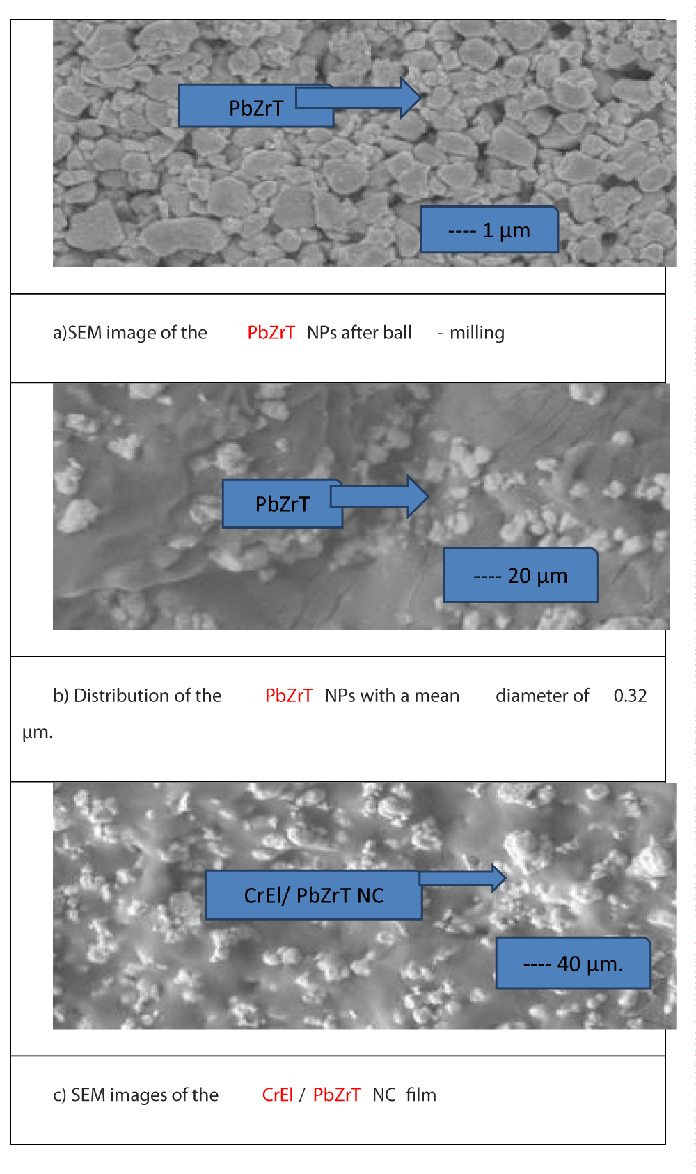
SEM was used to characterize the size and size distribution of P PbZrT NPs, and the dispersity of the PbZrT in CrEl NPs. FTIR spectroscopy was performed KBr pellets. For the measurement of the pyroelectric performance, a high-power light bulb was used to change the temperature of the film, and the distance between the film and the light bulb was maintained at 25 cm to obtain a constant heating rate. The temperature was monitored by a hermal imager. The open-circuit voltage and the short-circuit current were measured by a DMM6500. Differential scanning calorimetry tests were performed on the TA Instruments. The CrEl/PbZrT NC film with 30.1 wt % PbZrT was cut into small pieces. Samples were heated and cooled at a ramping rate of 15 °C/min under N2 for two cycles, from −60 °C to 160 °C. The chemical composition of PbZrT NC was measured by an electron microscope with an energy dispersive X-ray spectrometer (Horiba, Japan).
Results
Generation of CrEl/PbZrT NCs
In the CrEl/PbZrT NC, PbZrT NPs generate the primary pyroelectricity, while the thermal stress is generated from the CrEl and emitted to PbZrT NPs to enhance the secondary pyroelectricity. The CrEl film is prepared by the two-step thiol-acrylate Michael addition reactions [29]. First, the CrEl monomer 1,4-bis-[4-(3-acryloyloxypropyloxy)benzoyloxy]-2-methylbenzene (RM), the chain extender 2,2′-(ethylenedioxy) diethanethiol (EDDT), and the cross-linker pentaerythritol tetrakis(3-mercaptopropionate) (PETMP) are mixed together with PbZrT NPs to enhance the surface methacrylate groups. A 0.9: 0.3:0.9 molar ratio of acrylates to thiols and a 12:0.9 molar ratio of EDDT to PETMP are added to enhance the flexibility. Then, dipropylamine (DPA), is added to the mixture, at 90 °C to prepare the polydomain samples. The monodomain samples are prepared by stretching the as-cast films to 100% strain before thermal curing. The monodomain alignment of the CrEl films is verified by the polarized optical microscope equipped with cross-polarizers. After mixing with, PbZrT NPs, they can show reversible elongation upon heating and cooling processes.
The polydomain and monodomain CrEl/PbZrT NC containing 30.1 wt % PbZrT are 1.0 and 1.7 MPa in the longitudinal direction, respectively. It is much smaller than that of PVDF, 1.6 to 2.8 GPa [30-32]. In most CrEl composites for actuation applications, nanofiller loadings are typically less than 4 wt %, above which the viscosity of the mixture is increased substantially, and thus, the nanofillers cannot disperse uniformly [33-35]. To address this issue, we surface modify PbZrT NPs with 3-(trimethoxysilyl)propyl methacrylate (TMSPMA), which can covalently cross-link with the CrEl matrix via the thiol groups [36]. As a result, a very high loading (10 to 60 wt %) of PbZrT NPs can be introduced in our CrEl matrix, which is important to generate larger electric signals.
FTIR analysis results of PbZrT NPs
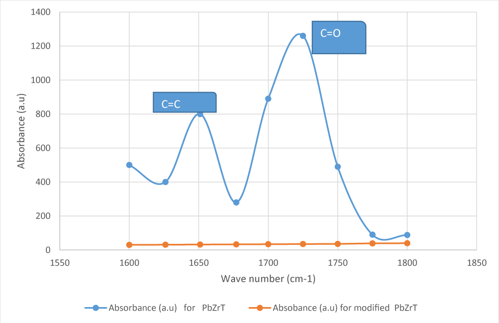
The Fourier transform infrared (FTIR) spectrum of the pristine PbZrT NPs exhibited disturbances for carbonyl and alkene groups at 1719 and 1642 cm−1, respectively (Figure 1). The modified PbZrT NPs clearly showed excellent surface functionalization (Figure 1).
Scanning Electron Microscopy (SEM) images of PbZrT and CrEl /PbZrT NCs
The scanning electron microscopy (SEM) images of PbZrT NPs and CrEl/ PbZrT Nanocomposites were illustrated in Figures 2a-2c. The mean diameter of the PbZrT NPs was approximately 258 nm and are randomly distributed in the CrEl matrix without exhibited an aggregation. At high loading, the covalent bonding between PbZrT NPs and the CrEl matrix improved the interfacial contact by facilitating the efficient transfer of thermal stress from CrEl to PbZrT NPs [37]. This is very important to built up a substantial secondary pyroelectric effect. It was used a thermal curing to provide an uniform cross-link in a thick film with a diameter of 1.2 mm.
The cross-linked CrEl /PbZrT NCs as films are placed between two copper films as the top and bottom electrodes (Figure 1c) for poling at an electric field of 1.4 kV mm−1 for 6 hours, aligning the dipole moments of bZrT NPs across the sample thickness. When the temperature changes, the primary pyroelectric effect of PbZrT, is doped with the secondary pyroelectric effect from the thermally induced stress in CrEl. This phenomenon is expected to provide power to an external circuit. In this way, the energy from temperature fluctuations in the surroundings can be harvested.
Energy-Dispersive Spectroscopy (EDS) analysis of PbZrT NC
EDS analysis was done to obtain chemical compositions of the PbZrT NC. Table 1 confirmed that PbZrT NC contains lead (Pb), zirconium (Zr), titanium (Ti), oxygen (O), and tin (Sn).
Pyroelectric harvesting from CrEl /PbZrT NCs
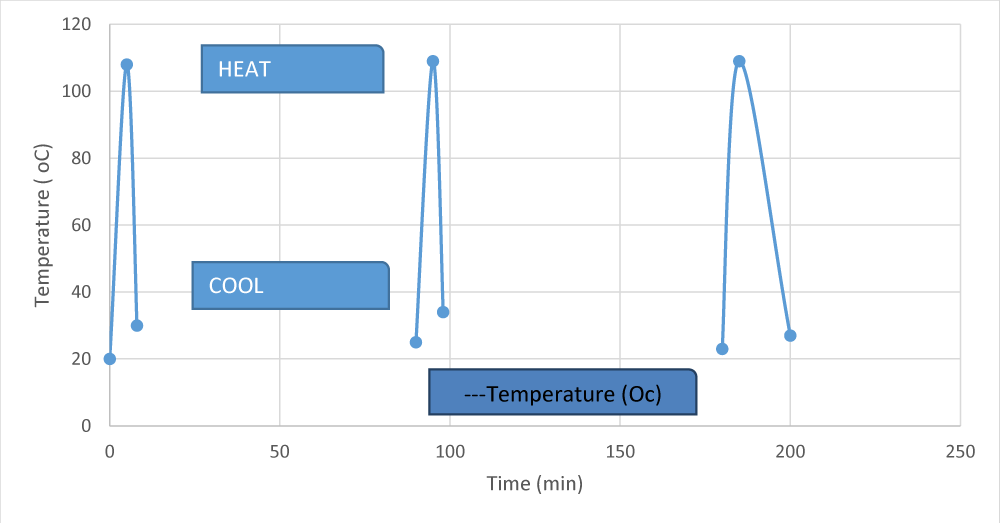
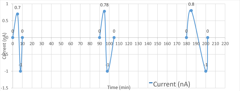
To detect the output current, the CrEl /PbZrT NCs is irradiated by a torch lamp every 8 min to heat and ten to cool for 100 min at temperatures between 20 °C and 70 °C (Figure 2a).
The cooling duration is long for the temperature to return to 20 °C after one cycle (Figure 2b).
It is noted that the peak temperature of 58 °C is above the TNI (52.5 °C) of the CrEl /PbZrT NCs LCE/PZT composite For pyroelectricity, the output current with Eq. (1).
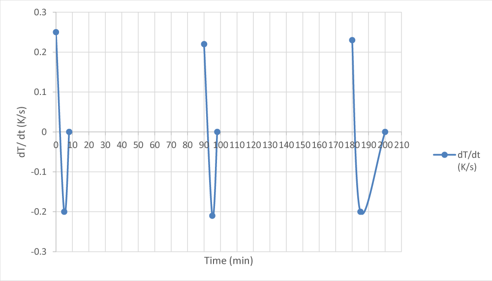
where A is the effective area of the pyroelectric device, and dTdt is the rate of temperature change. Since p and A are fixed for a certain system, the output current should have a similar profile as dTdt, which is calculated with a maximum heating rate of 0.25 K s−1 (Figure 2c) at CrEl /PbZrT NCs containing 30.3 wt % PbZrT NCs (Figure 2c).
In Figure 2c, the peak of the output current of 0.76 nA at the maximum heating rate of 0.20 K s−1, and the current changes direction when the dT/dt changes its sign. The voltage profile is also measured with a peak voltage of 9.8 mV when the internal impedance of the voltmeter is 12 megohms (Figure 2c).
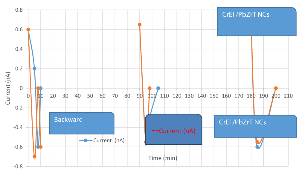
Since the output voltage of the pyroelectric materials is highly dependent on voltmeter parameters, a voltmeter with a larger impedance (12 gigohms) is used to record the peak voltage of 6.88 V. Due to CrEl /PbZrT NCs has polarization, we inverse the connection of the upper and bottom surfaces to get the forward and backward current. In this step the electric emittion originated from CrEl /PbZrT NCs (Figure 2d).
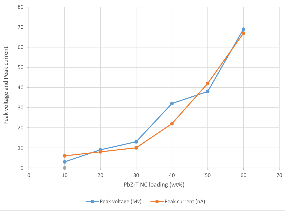
In all samples the PbZrT NC loading was 30.2 wt %. As the PZT loading is increased from 18.9 to 30.2, 45.9, and 65.9 wt %, respectively, the peak open-circuit voltage increases from 4.0 to 9.3, 21.3, and 27.4 mV, respectively. Simultaneously, the short-circuit current increases from 0.60 to 1.92 nA (Figure 2e).
At the highest loading of 65.1 wt %, p is calculated to be −3.80 nC cm−2 K−1, whose magnitude is 29% higher than that of the widely used flexible pyroelectric polymer PVDF (−2.99 nC cm−2 K−1) [13]. Pure CrEl shows no noticeable fluctuations in both current and voltage confirming the signals in CrEl /PbZrT NC films are generated by the pyroelectric effect instead of thermal stress from PbZrT itself.
Pyroelectric output emissions in on CrEl bonding
Since the secondary pyroelectricity here relies on the intimate interactions between CrEl and PbZrT NC films, the CrEl boundary conditions of the film (fixed or not fixed at ends) can affect the pyroelectric output. When CrEl /PbZrT NC film, the monodomain samples the disturbances shows a aaximum stress of 0.76 MPa, while the polydomain sample shows no apparent stress (Figure 3a).
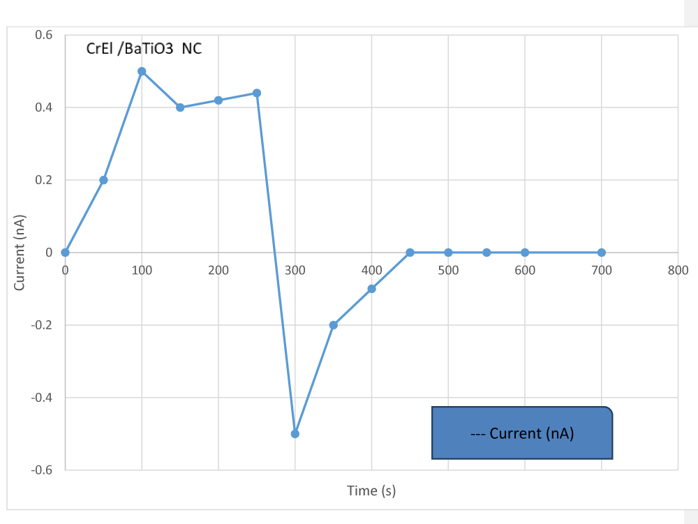
When PbZrT NCs are changed to BaTiO3 NPs, the remaining can be dispersed homogenously in the CrEl NPs. The polydomain CrEl to BaTiO3 ratio was 30.2 wt % with a peak current of 0.65 nA (Figure 3b). It is smaller than that of the polydomain CrEl /PbZrT NC film with a mass ratio of 37.1 wt %. This is because BaTiO3 has a lower magnitude of p (−20.0 nC cm−2 K−1) compared to that of PbZrT NCs (−26.8 nC cm−2 K−1) [5].
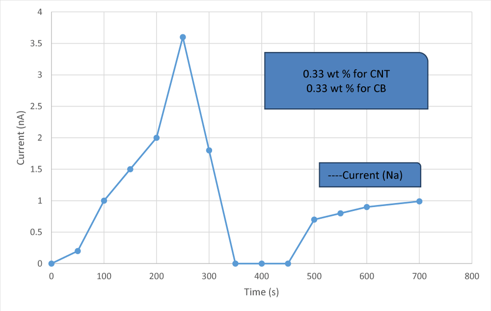
Further increase of the peak current, electrically conducting dopants can be added to reduce the resistance of the composite. For example, 0.27 wt % carbon nanotubes (CNTs) and 0.20 wt % carbon black (CB) are added to the polydomain CrEl /PbZrT NC with a ratio of 31.1 wt. Under these conditions can be found a peak current of 3.20 nA (Figure 3c). CNTs enhance conductivity, while the addition of CB makes the prepolymer processable instead of doubling CNT loadings as CNTs can substantially increase the viscosity [21].
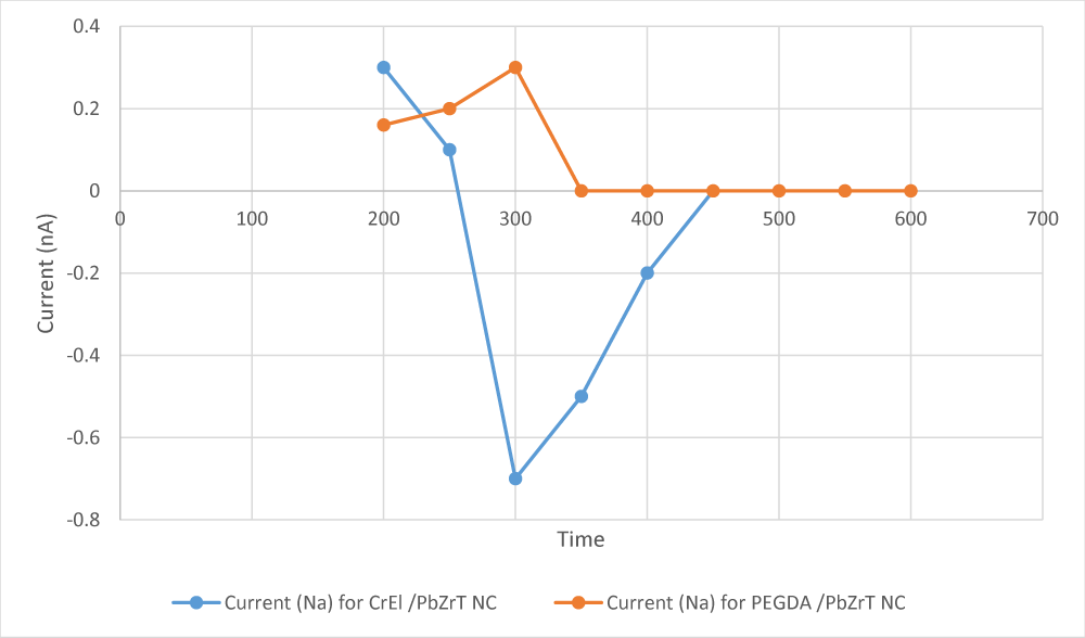
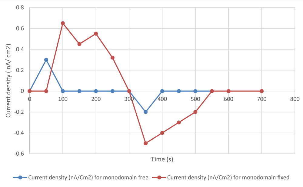
It is expected that different stresses lead to different secondary pyroelectricity. Even at the same CrEl alignment, whether the two ends of the film in the longitudinal direction are fixed or not can alter the output current. For the monodomain CrEl /PbZrT NC, the peak current density is 0.59 nA/cm2 with two ends fixed but 0.33 nA/cm2 with two ends free (Figure 4a).
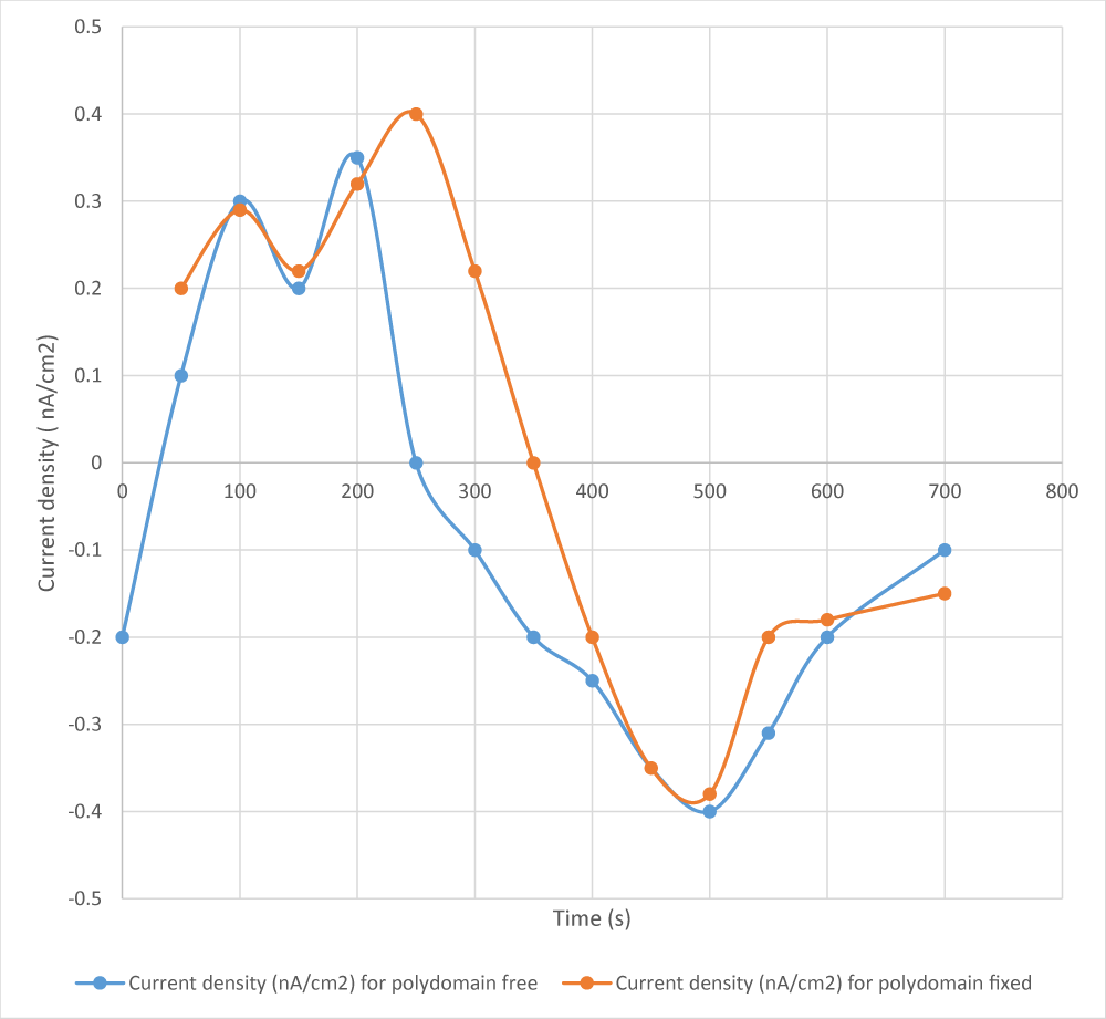
In the polydomain CrEl/PbZrT NC, the peak current density does not vary significantly: 0.38 nA/cm (fixed) and 0.35 nA/cm (free) (Figure 4b).
When the CrEl /PbZrT NC film is heated with a positive value, a negative secondary pyroelectric coefficient will enhance the output current. Now, we conclude that the output current density is higher than the primary contribution, 0.33 nA/cm2. Theoretical calculations give the estimated output current density of ~0.55 nA/cm2, which matches with experimental results of 0.54 nA/cm2.
This approach can be extended to other boundary conditions, for example, a monodomain CrEl /PbZrT NC film with all ends free. Theoretically, the average stresses from all directions are close to zero, although experimentally, it is difficult to meet this. The output current density should be close to the pure primary contribution, 0.33 nA/cm2, which matches with the experimental result, 0.32 nA/cm2.
Since the secondary pyroelectricity is dependent on intimate interactions between PbZrT NCs and CrEl NPs, both the disturbances of CrEl and the boundary conditions of the CrEl /PbZrT NC can affect the pyroelectric level. When CrEl /PbZrT NC is fixed at two ends, the monodomain sample shows a peak stress of 0.57 MPa, while the polydomain sample shows no apparent stress (Figure 4a). It is expected that different stresses lead to different secondary pyroelectricity. Even at the same CrEl alignment, whether the two ends of the film in the longitudinal direction are fixed or not can alter the output current. For the monodomain CrEl /PbZrT NC, the peak current density is 0.54 nA/cm2 with two ends fixed but 0.28 nA/cm2 with two ends free (Figure. 4b). However, for the polydomain LCE/PZT, the peak current density does not vary much: 0.35 nA/cm2 (fixed) and 0.34 nA/cm2 (Figure 4c). To investigate the contributions from the primary and secondary pyroelectricity of the LCE/PZT system, we carry out a quantitative analysis as follows.
Changing the boundary conditions alters the stress state inside the material and produces different secondary currents Isec. The stresses and deformations of monodomain CrEl /PbZrT NC under the two boundary conditions are shown in Figures 4a,4b as aforementioned above. The greater von Mises stresses make the secondary effect more prominent in the fixed-end condition than in the free-end condition. More importantly, the primary and secondary effects are synergistic in the fixed-end condition, and their currents are in the same direction, whereas in the free-end condition, the two effects are canceling of each other due to the change in the direction of the stress vector S. According to the simulation results, the peak total current density generated from the monodomain CrEl /PbZrT NC under the fixed-end and free-end conditions are 0.49 nA and 0.33 nA, respectively. Compared with the experimental results, the deviations are 19% and 2%, respectively.
Finite element method (FEM) simulations
Ferroelectric-type pyroelectric materials demonstrate a primary pyroelectric effect when there is a variation in temperature while the shape and volume remain constant. Nevertheless, this effect is often accompanied by a secondary effect that arises from thermal expansion and piezoelectricity, making it challenging to differentiate them in experiments. To quantify their respective contributions, it is necessary to perform FEM simulations using tools such as a Multmputer physic programme. The Heat Transfer in Solids module simulates the heating and cooling processes of the CrEl /PbZrT NC for a specific temperature boundary condition T(t) (Eq.2).
The simulations are conducted assuming zero strain in the out-of-plane direction, which is the case of LCE upon heated above TNI. Here, dz is the width of the samples, is the material density, Cp is the heat capacity, and u is the velocity field. The Pyroelectricity multiphysics interface can then be used to calculate the current density resulting from the temperature change dT/dt, under fixed-end and free-end conditions, according to Eq. 3
Where J represents the current flux, P stands for the material polarization, To is the initial temperature, and pET is the total pyroelectric coefficient. Specifically, pET is defined as pET = pES+eESα , where pES denotes the primary pyroelectric coefficient measured at constant strain. The second term in the equation is generally called the secondary coefficient, with piezoelectric coupling matrix eES and coefficient of thermal expansion α. The Electrostatics (es) and Electrical Circuit (cir) modules establish fundamental electrical laws and output signals. The Solid Mechanics (solid) and Thermal Expansion (te) modules are used to calculate the thermal strain sth = α[T(t)-T0] caused by the temperature change, as well as the corresponding thermal stress σ th=cEε th, where cE is the stiffness tensor of the material. Then, Piezoelectric Effect (pze) interface can be implemented to calculate the piezoelectricity-induced polarization based on the linear piezoelectric constitutive equations 4 and 5,
S = sE σ + dT E (4)
D = d σ+ εT E (5)
This equation expresses the relation between strain S, stress σ, electric field E, and electric displacement field D, where sE represents the elastic compliance tensor under constant electric field, defined as sE = cE -1 , d is the piezoelectric constant tensor, and εT denotes the dielectric constant tensor.
The primary pyroelectricity is related to the material’s intrinsic property, quantified with the primary pyroelectric coefficient, which has a negative value since electric displacement decreases at higher temperatures when dipoles become more isotropic. Therefore, the primary contribution of pyroelectricity in all four cases (polydomain versus monodomain, ends fixed or not) should be the same, which is 0.32 nA/cm2 from the calculation. Therefore, we focus on the differences in secondary pyroelectricity, which is piezoelectricity in essence, and whether the secondary effect works synergistically or counteracts with the primary effect when the film is subjected to different boundary conditions. First, we investigate the monodomain CrEl /PbZrT NC. When the external electric field E is neglected, the strain-charge form of pyroelectricity can be defined by Eq. 6.
where is the average electric displacement, d is the piezoelectric coefficient, and is the average stress. While a soft matrix embedded with stiff inclusions has a complex stress state at the microscale because of the interfacial contributions and phase mismatches, the primary interest in pyroelectric applications is the overall electrical output (e.g., current and ). Consequently, we use the average stress of the entire composite structure in this estimation approach without modeling the intricate local stress field σ (x, t). Since the output current in the z direction is measured, the third component of the average electric displacement, , can be described by Eq. 7.
Plugging in the parameters for PbZrT NC, it was obtained Eq.8
For a monodomain CrEl /PbZrT NC fixed at two ends in the x direction (Figure 4a), the local stresses in the y and z directions tend to cancel out since the film can freely deform in these directions. Therefore, compared to , the average tresses and are approximately zero. Thus, it can can estimate the secondary pyroelectric coefficient by Eqs. 8 and 9.
When the CrEl /PbZrT NC is heated with a positive value of σ ∂ σ 13∂T, a negative secondary pyroelectric coefficient will enhance the output current. Now, we conclude that the output current density is higher than the primary contribution, 0.32 nA/cm2. Theoretical calculations give the estimated output current density of ~0.50 nA/cm2 (with fixed ends), which matches with experimental results of 0.54 nA/cm2. The slightly higher value from experiments may come from the nonuniform stress distributions at the microscale.
This approach can be extended to other boundary conditions, for example, a monodomain CrEl /PbZrT NC with all ends free). Theoretically, the average stresses from all directions are close to zero, although experimentally, it is difficult to meet this. Given that ≈ 0 and p2 ≈ 0, the output current density should be close to the pure primary contribution, 0.30 nA/cm2, which matches with the experimental result, 0.29 nA/cm2.
The discussion on the monodomain CrEl/PbZrT NC can be partly applied to the polydomain CrEl /PbZrT featured by the interactions between the CrEl and PbZrT NC. In a polydomain phase, since each LC domain is oriented randomly against each other, the overall interactions are canceled out, resulting in little overall secondary pyroelectricity. Therefore, the output current density for the polydomain CrEl /PbZrT NC should be around 0.33 nA/cm2, which is purely the contribution from the primary pyroelectricity, regardless of whether the film is fixed or not. The current density obtained from experiments (0.36 to 0.38 nA/cm2) is slightly higher than the calculation, which may be attributed to residual orders in the polydomain film.
The secondary contribution to pyroelectricity is dependent on CrEl alignment and the boundary conditions. The monodomain CrEl /PbZrT under fixed boundary conditions shows the highest secondary effect that enhances the overall pyroelectricity. The polydomain CrEl /PbZrT shows weak secondary effects according to experiments. Nonfixed monodomain CrEl /PbZrT has reduced overall pyroelectricity. We note that all the discussions above are based on the composite films with 30.1 wt % PbZrT loading, and the highest possible PbZrT loading is 44.7 wt % instead of 60.1 wt % for the monodomain CrEl /PbZrT NC since the samples at higher PbZrT loadings crack when stretched. Under fixed boundary conditions, the monodomain CrEl /PbZrT NC (44.7 wt % PbZrT ) shows a peak output current of 2.81 nA and a voltage of 6.23 V, yielding a pyroelectric coefficient of −4.09 nC cm−2 K−1, whose magnitude is 52% higher than that of the widely used flexible pyroelectric polymer PVDF (−2.40 nC cm−2 K−1) (13).
The effect of CrEl NC mechanical properties on the pyroelectric performance of CrEl /PbZrT NCs
Whether the mechanical property of the CrEl NC affects the pyroelectric performance depends on the CrEl disturbances. For polydomain CrEl /PbZrT NC, the mechanical property of the CrEl NC has no a significant influence on the pyroelectric performance. That is because they have little secondary pyroelectricity due to the little thermal stress generated in polydomain CrEl. Therefore, the pyroelectric output of polydomain CrEl /PbZrT NC all comes from the primary pyroelectricity, which only relies on the mass loading of PbZrT NC. Similarly, for monodomain CrEl /PbZrT NC with free boundary conditions, the secondary pyroelectricity is nearly zero due to the negligible average stress. For monodomain CrEl /PbZrT NC with the two longitudinal ends fixed, the mechanical property of the CrEl NC can affect the pyroelectric performance, since the secondary pyroelectricity makes a difference now. A higher Young’s modulus can give a higher thermal stress, thus enhancing the secondary pyroelectricity. A higher thermal expansion coefficient gives a larger thermal strain, which leads to enhanced thermal stress and secondary pyroelectricity. However, in real cases, the Young’s modulus and thermal expansion coefficient change simultaneously, making it difficult to decouple their separate effect. Therefore, to test the effect of CrEl NC mechanical properties on the pyroelectric performance in real situations, we fabricated monodomain CrEl /PbZrT NC with a PbZrT ratio of 31.1 wt% with different molar ratios of PETMP. It was measured their Young’s moduli and their thermal expansion coefficients It was measured their pyroelectric currents, and conducted FEM simulations using the measured parameters as new input to verify the experiments. The results are summarized in Table 2. When the molar ratio of EDDT to PETMP was low (e.g., 9.6 in, the relatively high amount of crosslinker PETMP would make the polymer brittle, which fractured during the two-step crosslinking process. When the molar ratio of acrylates to thiols was too high, the degree of polymerization was too low to form a film after the Michael addition reaction, thus the two-step crosslinking could not proceed. It was detected that monodomain films were produced successfully. When the molar ratio of EDDT to PETMP was the highest, the lowest Young’s modulus was obtained as 0.66 MPa, and reduced secondary pyroelectricity was observed. Meanwhile, a lower Young’s modulus led to a higher absolute value of thermal expansion coefficient, which enhanced the secondary pyroelectricity. Therefore, Young’s modulus and thermal expansion coefficient counteract with each other regarding the secondary pyroelectricity. This proves again that they cannot be decoupled. For the pyroelectric current density, give the highest experimental results of 0.59 nA/cm2 .It was observed that the highest current density was obtained .Therefore, we can conclude that the effect of the Young’s modulus dominates. When the Young’s modulus was either too high or too low the fabrication of the the monodomain films were not performed.
Conclusion
The generation of CrEl/PbZrT pyroelectric energy harvester significantly enhanced pyroelectricity because of the secondary pyroelectricity generated from CrEl thermal stress. The effect of secondary pyroelectricity on the overall pyroelectric output is dependent on CrEl boundary conditions. The monodomain CrEl /PbZrT under fixed boundary conditions exhibits the highest secondary pyroelectric effect, with the output current density increased from 0.38 nA/cm2 to 0.64 nA/cm2.
The fixed monodomain CrEl/K−1 K−1PbZrT NC film with a PbZrT ratio of 49.9 wt % exhibited an output current of 3.22 nA and a voltage of 6.89 V at a maximum heating rate of 0.25 K s−1, which is 54% higher than that of the widely used flexible pyroelectric polymer PVDF. The CrEl /PbZrT NCs can be used as a power source to harvests the heat to drive flexible electronics such as LEDs, digital watches, and sensors.
Liquid crystalline elastomer (CrEl) and pyroelectric lead zirconate titanate (PbZrT) nanoparticles demonstrate a flexible heat harvesting device with high output. The overall pyroelectricity is enhanced by the secondary pyroelectricity generated from the thermal stress imposed on the CrEl.
- Mahapatra SD, Mohapatra PC, Aria AI, Christie G, Mishra YK, Hofmann S, et al. Piezoelectric materials for energy harvesting and sensing applications: roadmap for future smart materials. Adv Sci (Weinh). 2021;8(17):e2100864. Available from: https://doi.org/10.1002/advs.202100864
- Sukumaran S, Chatbouri S, Rouxel D, Tisserand E, Thiebaud F, Ben Zineb T. Recent advances in flexible PVDF based piezoelectric polymer devices for energy harvesting applications. J Intell Mater Syst Struct. 2021;32:746-780. Available from: https://doi.org/10.1177/1045389X20966058
- Khan MSA, Hoq MT, Karim AHMZ, Alam MK, Howlader M, Rajkumar RK. Energy harvesting-technical analysis of evolution, control strategies, and future aspects. J Electron Sci Technol. 2019;17:116-125. Available from: https://doi.org/10.11989/JEST.1674-862X.80314201
- Sahu M, Hajra S, Lee K, Deepti P, Mistewicz K, Kim HJ. Piezoelectric nanogenerator based on lead‐free flexible PVDF‐barium titanate composite films for driving low power electronics. Crystals. 2021;11:1-10. Available from: https://doi.org/10.3390/cryst11020085
- Ghosh SK, Mandal D. Synergistically enhanced piezoelectric output in highly aligned 1D polymer nanofibers integrated all-fiber nanogenerator for wearable nano-tactile sensor. Nano Energy. 2018;53:245-257. Available from: https://doi.org/10.1016/j.nanoen.2018.08.036
- Mistewicz K. Pyroelectric nanogenerator based on an SbSI-TiO2 nanocomposite. Sensors (Basel). 2021;22(1):69. Available from: https://doi.org/10.3390/s22010069
- Bowen CR, Taylor J, Leboulbar E, Zabek D, Chauhan A, Vaish R. Pyroelectric materials and devices for energy harvesting applications. Energy Environ Sci. 2014;7:3836-3856. Available from: https://pubs.rsc.org/en/content/articlelanding/2014/ee/c4ee01759e
- Lang SB, Das-Gupta DK. Chapter 1 – Pyroelectricity: Fundamentals and Applications. 2001. Available from: https://doi.org/10.1016/B978-012513745-4/50036-6
- Lang SB. Pyroelectricity: from ancient curiosity to modern imaging tool. Phys Today. 2005;58:31-36. Available from: https://ui.adsabs.harvard.edu/abs/2005PhT....58h..31L
- Korkmaz S, Kariper A. Pyroelectric nanogenerators (PyNGs) in converting thermal energy into electrical energy: fundamentals and current status. Nano Energy. 2021;84:105888. Available from: https://doi.org/10.1016/j.nanoen.2021.105888
- Thakre A, Kumar A, Song HC, Jeong DY, Ryu J. Pyroelectric energy conversion and its applications—flexible energy harvesters. Sensors (Basel). 2019;19:1-25. Available from: https://doi.org/10.3390/s19092170
- Xue H, Yang Q, Wang D, Luo W, Wang W, Lin M, et al. A wearable pyroelectric nanogenerator and self-powered breathing sensor. Nano Energy. 2017;38:147-154. Available from: https://doi.org/10.1016/j.nanoen.2017.05.056
- Yang Y, Zhang H, Zhu G, Lee S, Lin ZH, Wang ZL. Flexible hybrid energy cell for simultaneously harvesting thermal, mechanical, and solar energies. ACS Nano. 2013;7:785-790. Available from: https://doi.org/10.1021/nn305247x
- Yang Y, Wang S, Zhang Y, Wang ZL. Pyroelectric nanogenerators for driving wireless sensors. Nano Lett. 2012;12(12):6408-6413. Available from: https://doi.org/10.1021/nl303755m
- Clementi G, Margueron S, Suarez MA, Baron T, Dulmet B, Bartasyte A. Piezoelectric and pyroelectric energy harvesting from lithium niobate films. J Phys Conf Ser. 2019;1407:012039. Available from: https://iopscience.iop.org/article/10.1088/1742-6596/1407/1/012039
- Yang Y, Jung JH, Yun BK, Zhang F, Pradel KC, Guo W, et al. Flexible pyroelectric nanogenerators using a composite structure of lead-free KNbO3 nanowires. Adv Mater. 2012;24:5357-5362. Available from: https://doi.org/10.1002/adma.201201414
- Wu CM, Chou MH, Chala TF, Shimamura Y, Murakami R. Infrared-driven poly(vinylidene difluoride)/tungsten oxide pyroelectric generator for non-contact energy harvesting. Compos Sci Technol. 2019;178:26-32. Available from: https://doi.org/10.1016/j.compscitech.2019.05.004
- Zabek D, Taylor J, Le Boulbar E, Bowen CR. Micropatterning of flexible and free standing polyvinylidene difluoride (PVDF) films for enhanced pyroelectric energy transformation. Adv Energy Mater. 2015;5:1-6. Available from: https://doi.org/10.1002/aenm.201401891
- He H, Lu X, Hanc E, Chen C, Zhang H, Lu L. Advances in lead-free pyroelectric materials: a comprehensive review. J Mater Chem C. 2020;8:1494-1516. Available from: https://pubs.rsc.org/en/content/articlelanding/2020/tc/c9tc05222d
- Lee JH, Lee KY, Gupta MK, Kim TY, Lee DY, Oh J, et al. Highly stretchable piezoelectric-pyroelectric hybrid nanogenerator. Adv Mater. 2014;26:765-769. Available from: https://doi.org/10.1002/adma.201303570
- Ruan L, Yao X, Chang Y, Zhou L, Qin G, Zhang X. Properties and applications of the β phase poly(vinylidene fluoride). Polymers (Basel). 2018;10. Available from: https://doi.org/10.3390/polym10030228
- Li Q, Zhao J, He B, Hu Z. Solution processable poly(vinylidene fluoride)-based ferroelectric polymers for flexible electronics. APL Mater. 2021;9. Available from: https://doi.org/10.1063/5.0035539
- Krishnamoorthy K, Mariappan VK, Pazhamalai P, Sahoo S, Kim SJ. Mechanical energy harvesting properties of free-standing carbyne enriched carbon film derived from dehydrohalogenation of polyvinylidene fluoride. Nano Energy. 2019;59:453-463. Available from: https://doi.org/10.1016/j.nanoen.2019.02.041
- Pazhamalai P, Krishnamoorthy K, Mariappan VK, Sahoo S, Manoharan S, Kim SJ. A high efficacy self-charging MoSe2 solid-state supercapacitor using electrospun nanofibrous piezoelectric separator with ionogel electrolyte. Adv Mater Interfaces. 2018;5:1800055. Available from: https://doi.org/10.1002/admi.201800055
- Mariappan VK, Krishnamoorthy K, Manoharan S, Pazhamalai P, Kim SJ. Electrospun polymer-derived carbyne supercapacitor for alternating current line filtering. Small. 2021;17:2102971. Available from: https://doi.org/10.1002/smll.202102971
- Saxena P, Shukla P. A comprehensive review on fundamental properties and applications of poly(vinylidene fluoride) (PVDF). Adv Compos Hybrid Mater. 2021;4:8-26. Available from: https://link.springer.com/article/10.1007/s42114-021-00217-0
- Low YKA, Meenubharathi N, Niphadkar ND, Boey FYC, Ng K. α- and β-poly(vinylidene fluoride) evoke different cellular behaviours. J Biomater Sci Polym Ed. 2012;23:1651-1667. Available from: https://doi.org/10.1163/092050610X519471
- Gusarov B, Gusarova E, Viala B, Gimeno L, Boisseau S, Cugat O, et al. Thermal energy harvesting by piezoelectric PVDF polymer coupled with shape memory alloy. Sens Actuators A Phys. 2016;243:175-181. Available from: https://doi.org/10.1016/j.sna.2016.03.026
- Panwar LS, Panwar V, Anoop G, Park S. Carbon nanofiber-polyelectrolyte triggered piezoelectric polymer-based hydrophilic nanocomposite for high sensing voltage generation. J Mater Res Technol. 2022;17:3246-3261. Available from: https://doi.org/10.1016/j.jmrt.2022.02.075
- Cai X, Lei T, Sun D, Lin L. A critical analysis of the α, β and γ phases in poly(vinylidene fluoride) using FTIR. RSC Adv. 2017;7:15382-15389. Available from: https://pubs.rsc.org/en/content/articlelanding/2017/ra/c7ra01267e
- Nishiyama T, Sumihara T, Sasaki Y, Sato E, Yamato M, Horibe H. Crystalline structure control of poly(vinylidene fluoride) films with the antisolvent addition method. Polym J. 2016;48:1035-1038. Available from: https://www.nature.com/articles/pj201662
- Panwar V, Kang B, Park J, Park S, Mehra RM. Study of dielectric properties of styrene-acrylonitrile graphite sheets composites in low and high frequency region. Eur Polym J. 2009;45:1777-1784. Available from: https://doi.org/10.1016/j.eurpolymj.2009.02.020
- Almond DP, Bowen CR. An explanation of the photoinduced giant dielectric constant of lead halide perovskite solar cells. J Phys Chem Lett. 2015;6:1736-1740. Available from: https://doi.org/10.1021/acs.jpclett.5b00620
- Panwar V, Gill FS, Rathi V, Tewari VK, Mehra RM, Park JO, et al. Fabrication of conducting composite sheets using cost-effective graphite flakes and amorphous styrene acrylonitrile for enhanced thermistor, dielectric, and electromagnetic interference shielding properties. Mater Chem Phys. 2017;193:329-338. Available from: https://doi.org/10.1016/j.matchemphys.2017.02.050
- Jayakumar OD, Abdelhamid EH, Kotari V, Mandal BP, Rao R, Jagannath, Naik VM, et al. Fabrication of flexible and self-standing inorganic-organic three phase magneto-dielectric PVDF based multiferroic nanocomposite films through a small loading of graphene oxide (GO) and Fe3O4 nanoparticles. Dalton Trans. 2015;44:15872-15881. Available from: https://doi.org/10.1039/c5dt01509j
- Dash S, Choudhary RNP, Kumar A, Goswami MN. Enhanced dielectric properties and theoretical modeling of PVDF–ceramic composites. J Mater Sci Mater Electron. 2019;30:19309-19318. Available from: https://link.springer.com/article/10.1007/s10854-019-02291-z
- Gupta S, Bhunia R, Fatma B, Maurya D, Singh D, Gupta R, et al. Multifunctional and flexible polymeric nanocomposite films with improved ferroelectric and piezoelectric properties for energy generation devices. ACS Appl Energy Mater. 2019;2:6364-6374. Available from: https://pure.psu.edu/en/publications/multifunctional-and-flexible-polymeric-nanocomposite-films-with-i
Article Alerts
Subscribe to our articles alerts and stay tuned.
 This work is licensed under a Creative Commons Attribution 4.0 International License.



 Save to Mendeley
