Introduction
Over the past few decades, offshore structures, such as oil platforms, offshore wind-power plants, have been in rapid growth in coastal and deep ocean regions, and wave-structure interaction has long been a strong interest in coastal and offshore engineering. A thorough understanding of the interaction of waves with offshore structures is vital in the safe and design of such structures. In addition, the flow field near the structures is helpful to understand the scour, sediment transport process in the coastal regions. In designing these structures, it is critical to be able to calculate wave forces acting on each individual structure.
Information on wave forces can be obtained by means of laboratory experiments or numerical simulations. Since laboratory experiments are usually constrained by the physical dimensions of laboratory facilities, it is not very often feasible to perform extensive parameter studies (e.g., variation of water depth, wave parameters, breaker type, etc.) even if the costs are of no concern. The alternative is to use numerical simulations as supplements to laboratory experiments, where accurate numerical simulations will also provide much more detailed insights into the physical processes that could not be achieved by experimental approach. In other words, a limited numbers of experiments can be designed so that the laboratory data can be effectively used to validate numerical models. The validated numerical models are then used to simulate scenarios with much wider range of physical parameters of interest.
So far, wide range of the numerical simulation models developed for wave propagation as the key concept in the maritime engineering which have been built upon the Navier-Stokes equations. One of these methods is the SPH method that has gradually matured over time into a suitable tool for computational fluid dynamics because of its flexibility to simulate complex problems such as flow through porous medium [1], multi-phase flows [2-4], heat conduction [5], free surface problems [6-8], fluid structure interactions [9,10], fuel cell [11], etc. However, compared with the Finite Difference (FD) or Finite Volume (FV) methods, SPH is still a relatively novel method in computational fluid dynamics and its shortcomings are still being improved. Shao and Lo [12], introduced ISPH algorithm based on the projection scheme. Numerical results have shown that ISPH produces reasonable accurate predictions of velocity and forces on solids.
Solitary wave generation is a traditional benchmark for numerical wave model tests. It is a permanent progressing wave form consisting of a single elevation above the undisturbed surface that propagates without the change of form on a constant still water depth over a flat bottom. A wide variety of analytical theories have been introduced for the solitary wave generation. It was first reported by Russell [13], who made remarkable experiments and gave an empirical relationship for the wave speed, which was later established theoretically, to the lowest order by Boussinesq [14] and Rayleigh [15], as part of an overall approximate solution. Since then, there have been several attempts to improve upon this solution, e.g. see [16-18]. Of the approximate solutions, several methods for the solitary wave have obtained series expansions in terms of wave amplitude, these being taken as far as the third order Grimshaw. He considered the one-dimensional modulations formed on the Boussinesq solitary wave and obtained third order equations analogous to those used by Boussinesq for the case of constant undisturbed depth in the higher order form [19]. Furthermore, an asymptotic solution was presented which described a slowly varying solitary wave [20]. An early work on WCSPH for solitary wave was done by Monaghan [21], while Lo and Shao used ISPH to generate solitary waves [22]. In this study, an ISPH method will be used to simulate the solitary wave generation and propagation in constant water depth.
Governing equations
The motion of a continuum in the Lagrangian description subjected to the action of body force in the isothermal condition, is represented by the continuity equation:
and the momentum equation:
Where p is density, t is time, vi is the velocity vector, xi is the position vector, fi is the body force vector, σij is the stress tensor and the notation implies summation over repeated indices. The stress tensor can be decomposed into deviatoric viscous stress tensor τij and isotropic pressure p, according to the following equation:
Where δij is the Kronecker delta. Pressure can be formally defined by the equation of state in the compressible flows, while for incompressible flows, it is derived from the divergence free condition of the velocity field. Assuming an incompressible Newtonian fluid, the continuity Equation (1) reduces to:
and the momentum Equation (2) will be:
Where ν is the kinematic viscosity. The conventional incompressible approach deals with pressure and velocity as primitive variables. The classical projection method [23] is used to calculate the pressure field and enforce incompressibility, simultaneously. The discretized form of the momentum equation is split into two parts. The first being the prediction step and is based on viscous and body forces. In this step, the intermediate velocity field
is obtained from velocity at (n)th time step:
In each time step, the intermediate velocity field is calculated for fluid and boundary particles. In the second step, correction step, pressure force is included:
The intermediate velocity field is usually not divergence free but this is imposed upon
. Hence, the intermediate velocity is projected on the divergence free space by taking the divergence of Equation (7) as:
where the ∇2 is the Laplacian operator. Once the pressure is obtained from pressure Poisson Equation (8), the velocity vector is updated by using the computed new pressure gradient:
Finally, particles are moved according to this corrected velocity as:
SPH interpolation
The foundation of mesh free SPH method is based on integral interpolants which represents that any field variable X can be calculated over a set of SPH particles on domain of interest in terms of its values by taking a good interpolation kernel function. The exact integral representation of field variable X is:
Where δ(r – r′) is Dirac delta function and Ω represents the computational domain. Equation (11) can be represented by defining a proper kernel function, W, with effective smoothing length h as:
In discrete notation, this approximation leads to the following approximation of the function at a interpolation particle a:
where b is all the particles within the kernel function’s support domain. mb and pb are the mass and density of particle b, respectively, and weight function or kernel is denoted by.
The parameter h is influence domain or smoothing domain, and controls the size of the area around particle a where contribution from the rest of the particles cannot be neglected. Considering the computational accuracy and efficiency [24], the following kernel function based on the cubic spline function and normalized in two dimensional is adopted:
where for two dimensional cases
. The gradient, divergence and Laplacian operators need to be formulated in ISPH algorithm. In the current work, the following commonly used forms are employed for gradient of a scalar A [25]:
and divergence of a vector u* [26]:
where
is the gradient of the kernel function with respect to particle a and calculated as:
Viscous term is discretized according to the relation given in [5]:
where
and
is a parameter to avoid a zero denominator. Also Laplacian equation is discretized according to the relation given in [27]:
Resolution of the linear systems are widely studied by mathematicians as the demand for an efficient and smoothly-converging solver increases from numerical simulations. There are numerous iterative methods that are widely used in academic and commercial codes to solve the Pressure Poisson Equation (PPE). Here two solvers, Conjugate Gradient (CG) and Bi-Conjugate Gradient (Bi-CG) [28,29], can be applied to solve PPE.
The computational domain is divided into square cells of side 2h. Thus, for a particle located inside a cell, only the interactions with the particles of the same cell and its neighbors need to be considered (only 9 cells in 2-D). The searching algorithm is applied at the beginning of each time step updating the particle’s neighbors and the corresponding kernel derivatives. The time step limit for this method is the minimum of three conditions, the CFL, the mass and the viscous force conditions such that [26]:
where fa is the force per unit mass, equivalent to the magnitude of particle acceleration and uref is the maximum fluid velocity in the domain [26].
Boundary condition handling
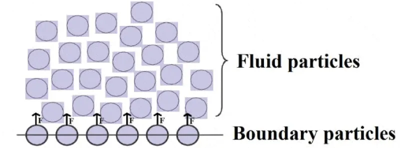
The Lagrangian nature of SPH method will cause the implementation of the boundary conditions less straightforward than in common mesh based methods. Different boundary conditions are used in the SPH method. In the present study, moving and stationary solid wall boundary conditions are used. There are different boundary types in SPH to simulate solid walls, namely the repulsive force [30], ghost or mirror particles [31] and dummy particles [12,32]. The repulsive force boundary condition, first proposed by Monaghan [30], uses forces similar to inter-molecular interactions. A force is exerted on a fluid particle having a distance r from a boundary particle, which has the form of Lennard-Jones potential. This force is increased as the distance r between a boundary and a fluid particle is decreased, preventing the fluid particles from penetrating the wall, Figure 1.
Figure 1: Sketch of repulsive force boundary condition.
The mirror particle method is used to enforce the no-slip as well as the Neumann boundary conditions. In this method the particles whose support domain is truncated by a solid boundary are reflected on the other side of the wall. The mirror or ghost particles have the same pressure as their corresponding fluid particles but have velocities extrapolated from the fluid and wall velocities.
One of the sources of inaccuracy in the SPH method is the truncation of the boundary particles. This means that, not enough particles might be present in the support domain of a fluid particle. The other method to model solid walls is the use of dummy particles. In this method several layers of dummy particles are placed parallel to the boundary particles. So, the support domain of the particles located close to the solid wall will not be truncated any longer. These layers of dummy particles are linked to their corresponding boundary particles and have the same pressure and velocity as their linked particles. In the present work, dummy particles are used to model solid walls.
The number of dummy particle layers are decided from the radius of the compact support. In the following simulations, three layers of dummy particles are used. Governing equations are solved only for fluid and boundary particles and the pressure and velocity (also intermediate velocity) of the dummy particles are updated to their corresponding boundary wall particles.
The velocity and the intermediate velocities are held constant on the boundary particles, but their pressure is calculated from the PPE equation. Afterwards, the pressure of the dummy particles are updated to their corresponding boundary particles. In this way the Neumann boundary condition on the walls is approximated.
Wave characteristics
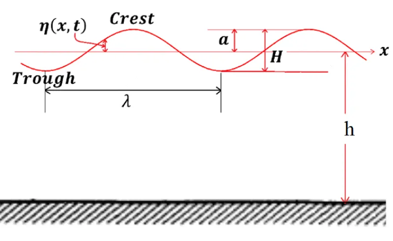
Three key parameters to identify waves are their lengths and heights, and the water depth over which they are propagating. All other parameters can be calculated from these quantities, e.g. wave induced water accelerations and velocities. A two dimensional schematic of a wave propagating in the x direction is shown in the Figure 2. The wave length, λ, is the horizontal distance between two successive wave troughs. This length is related to the water depth,h, and wave period, T, which is the time required for two successive troughs to pass a particular point. As the wave moves a distance λ, in time T, its speed called celerity is defined as C =λ/ T.
Figure 2: Schematic wave representation.
Solitary waves in constant water depth
Two dimensional dam break flow is chosen as the first suitable validation test case. Dam break flows over dry and wet beds have attracted wide research areas due to their theoretical, engineering and scientific considerations. If a dam break occurred over a dry bed, the generated wave is described by a tongue of water extended rapidly along the dry bed and if dam flows toward downstream over the wet bed, the attributed fluid flow features become remarkably different and some vorticity is developed at the front of the dam break. As a result, characteristics of the fluid flow are represented by the wave generation, wave crest development, wave breaking, and its impact with the downstream calm water and strew of water that generates some splash-up flow. Due to these features, dam break over the wet bed is an interesting benchmark to validate the numerical methods [33,34].
Solitary wave propagation in constant water depth is a classical benchmark problem for numerical wave model test. It propagates without the change of form in constant water depth over a flat bottom. Different analytical theories are already developed for the solitary wave. Therefore, it is well suited to evaluate the accuracy of the numerical model. For example, by checking the free surface location, the quality of volume tracking algorithm can be evaluated. In the numerical simulation, the free surface elevation and velocity distribution prescribed on the incident wave boundary are calculated by Third-order Grimshaw solitary wave solution [20,35]:
where ε = H/h; H is the wave height; h is the still water depth;
;
;
in which C is the wave speed; the coefficient α:
and the wave speed C is:
and the velocity distribution is:
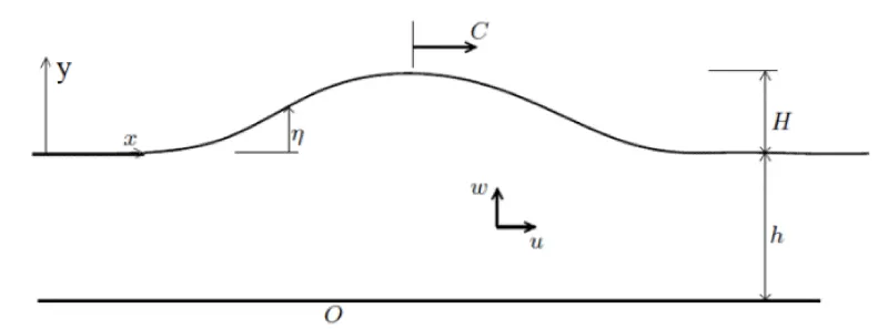
The coordinate system is defined in Figure 3. The Grimshaw solution is well suited for solitary wave of
.
Figure 3: Solitary wave representation.
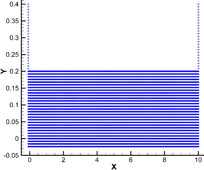
The Third order Grimshaw solitary waves is simulated to be compared with the analytical theory. Here two still water depths of h=0.2 m and h=0.3 m are assumed (Figure 4) and the dimensionless height of desired wave ranging from
to
h = 2.0 m are simulated, where particle resolution of 37000 and 77000 are used for the water depths of h=0.2 m and h=0.3 m, respectively. The computational domain is 50h in the stream wise direction x and 2h in the vertical direction y. In the stream wise direction, 1260 and 1860 particles with uniform grid size of
are used, while we use 50 and 75 particles in the vertical direction in two cases, respectively. The fluid has a density of
and kinematic viscosity of
.Three layers of dummy particles are used to handle the wall boundary condition.
Figure 4: Initial particle distribution of solitary wave generation test case for h = 0.2 m h=0.2 m.
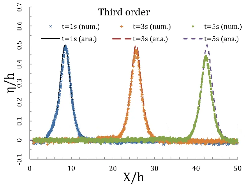
Figure 5 shows the free surface elevation profiles at three different times (1, 3 and 5 seconds from beginning of the simulation) corresponding to solitary waves generated using the Third order Grimshaw method for a water column with
and
. It is noticeable that compared with the analytical solution, the wave profile heights are decreased as it follows throughout the channel. The discrepancy between the predicted and analytical heights are 10% when the wave propagates along the channel for first 5 seconds.
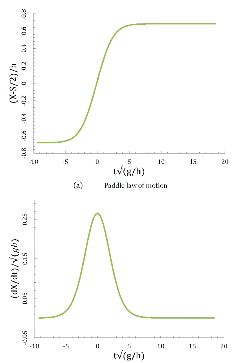
On Figure 6(a), the paddle laws of motion corresponding to the Third order wave generation is plotted for
for a water column with
. Greatest accelerations occur somewhere between the beginning of motion (zero velocity) and mid-stroke (maximum velocity). Qualitatively, the larger the maximum velocity and the shorter the duration of motion, the greater the acceleration. For the same wave we also plot on Figure 6 (b) the dimensionless paddle velocity corresponding to this law of motion. The maximum nondimensionalized velocity of 0.27 is observed.
Figure 5: Solitary wave profile comparisons with analytic ones at various times for ε=0.4 and a water column of h=0.3 m.
Figure 6: Paddle motion for E = 0.2 and a water column of h=0.3 m.
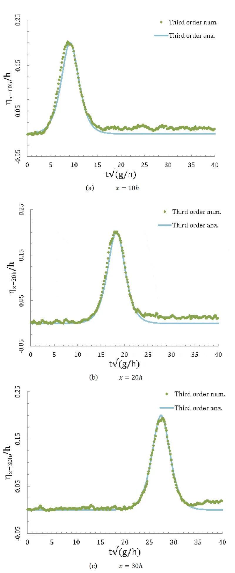
Measurements of the free surface elevation at different distances from the paddle for a solitary wave of desired dimensionless amplitude
in a water column of
where was generated using Third order numerical integration are plotted on Figure 7. The solitary wave amplitude is decreases slowly as it travels along the channel.
Figure 7: Comparison of record of free surface elevation at different distances from the paddle with analytic ones.
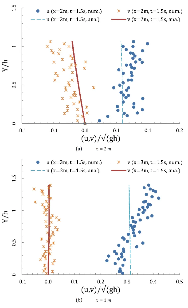
Figure 8 shows the nondimensionalized velocity component variations versus nondimensionalized vertical coordinate of the wave at
from the beginning of the simulation for two locations (
and
regarding the initial paddle location). The velocity profiles are close to the analytic ones. Near the water surface, under both wave surfaces, the measured particle horizontal velocity is somewhat greater than the theoretical values, while the vertical velocity components is underestimated compared with the analytic ones, the reason of which may be due to the particle resolution.
Figure 8: Comparisons of velocity components with analytical results at t=1.5 s at different distances away from the paddle initial location.
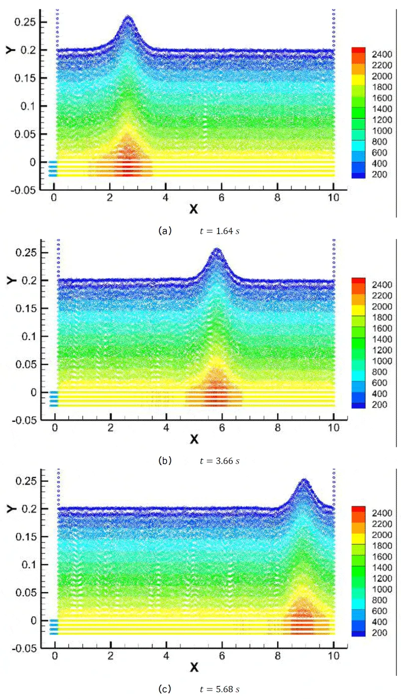
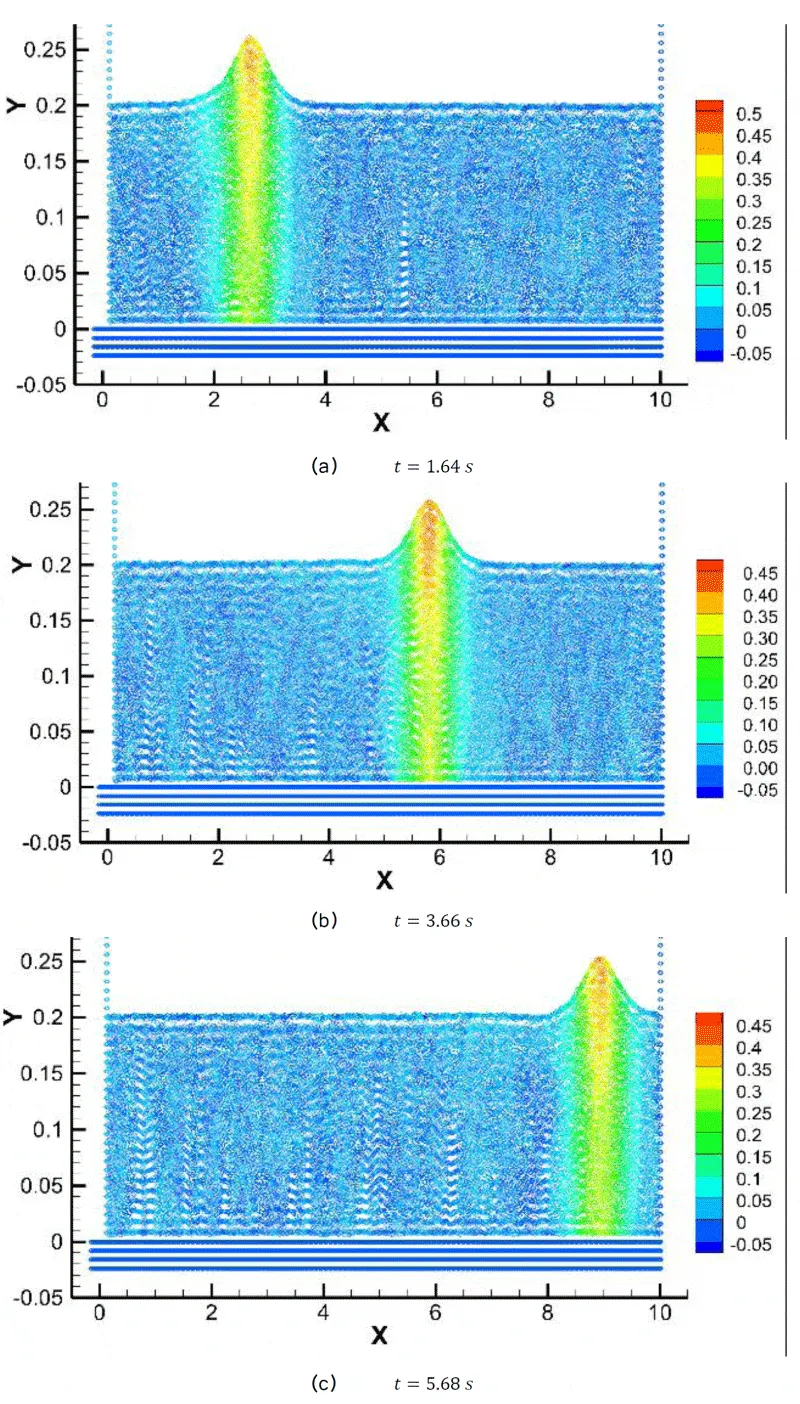
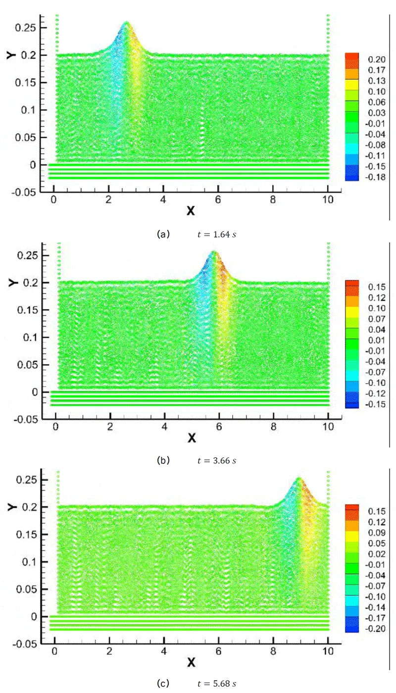
The flow field contours at three different times are illustrated in Figures (9-11) for the
case for a water column of
. h = 2.0m As seen, the pressures are captured precisely and the pressure distributions under the wave crests are accurately predicted, Figure 9. The wave speed at this case is
,
that proves the wave crest propagation at these selected times, where the wave crest transferred to x = 2.61 m, x = 5.83 m and x = 9.05 m, respectively, Figure 10. Furthermore, the symmetric behavior of the vertical velocity at the wave is noticeable at these selected times, Figure 11.
Figure 9: Solitary wave pressure contour.
Figure 10: Solitary wave horizontal velocity contour.
Figure 11: Solitary wave vertical velocity contour.
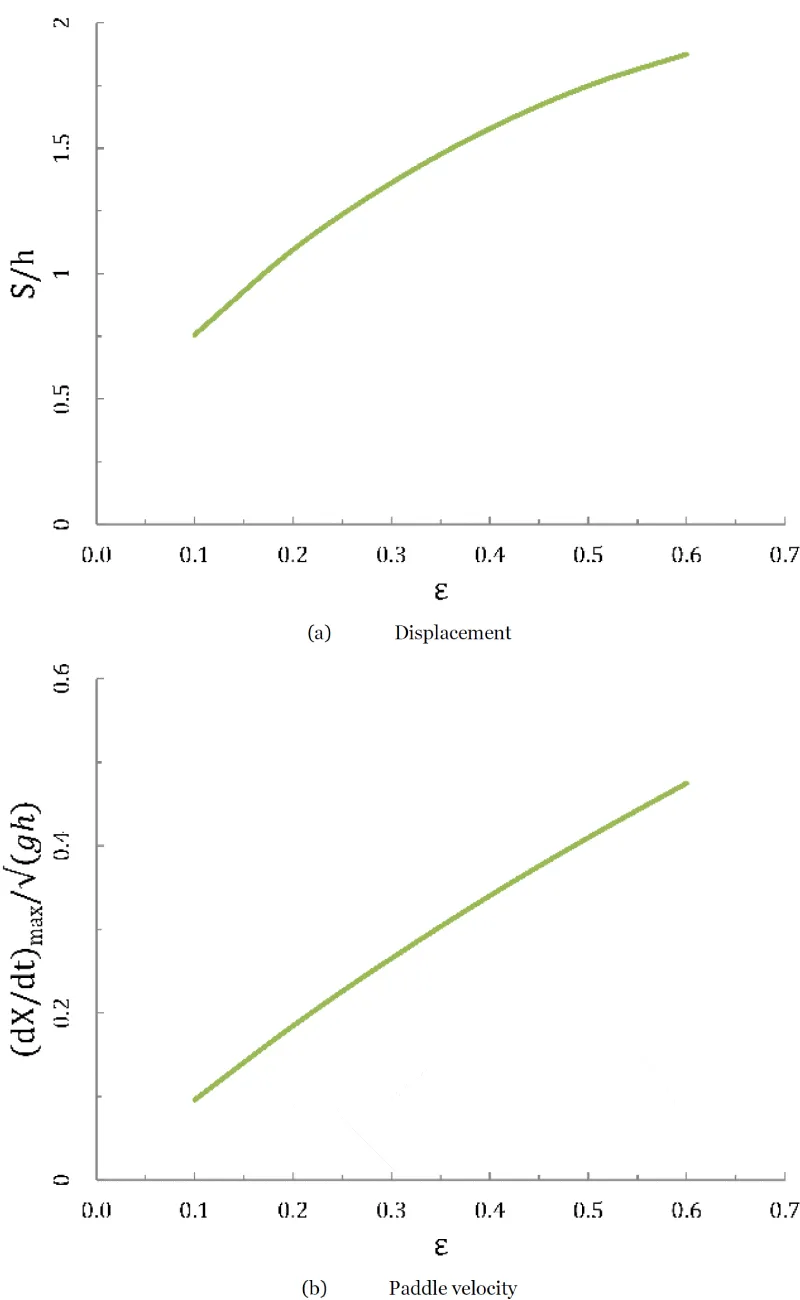
In order to investigate the solitary wave generated behavior on the pureness of the generated wave on other wave heights, this problem is solved for a wide range of the desired wave heights,
. As expected, greater the desired wave height, the greater amount of the water volume must be pushed. Figure 12(a) illustrates the depth averaged net mass displacement L of a solitary wave. This net mass displacement is the total stroke of the paddle prescribed in each procedure. The rate of the displacement increment is decreased as the desired wave height is increased. Furthermore, the maximum paddle velocity (which occurs at mid-stroke) is obtained for this range of wave heights. Again, the slope of the maximum paddle velocity is decreases as dimensionless amplitude increases.
Figure 12: Maximum paddle velocity and displacement for a solitary wave with h=0.3 m.
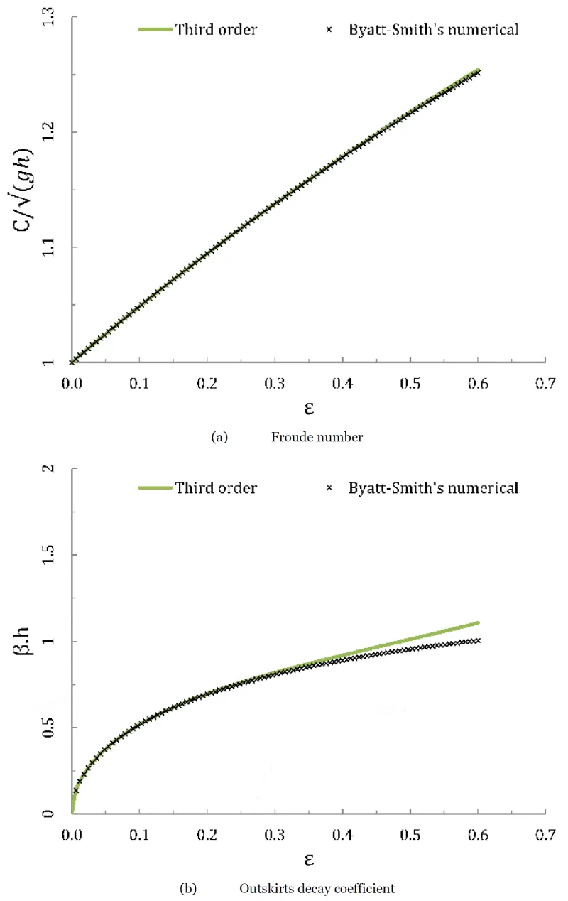
The dimensionless phase speed (or Froude number,
) is plotted on Figure 13(a) for the selected wave height range. It shows that the Third order method phase speed is matches to the Byatt-Smith numerical estimation in the studied range of ε. The dimensionless outskirts decay coefficient
versus the dimensionless amplitude is plotted on Figure 13(b). This outskirts decay coefficient describes the way free surface elevation tends towards the mean level at infinity. Stokes showed that
is a solution of the following equation, also used by Byatt-Smith [36]:
Figure 13: Wave parameters for a solitary wave with h=0.3 m. The Byatt-Smith’s numerical solution [36] is plotted as stars.
As a matter of fact the Third order method for
matches the Byatt-Smith reference but for greater
some discrepancy is observed.
Conclusion and Future Works
The ISPH numerical method is used to simulate the solitary wave generation and propagation along the channel at different wave amplitudes and water depths in an ISPH-based numerical wave flume. The numerical results are compared with analytical data in terms of free surface displacements, fluid particle velocity, phase speed, flow field counters and some other wave parameters.
In the first section, the free surface profile variations over time, position and through solitary wave amplitude ranges are assumed. The numerical free surface profiles are compared with analytical results at various times and it is proved that studied Grimshaw Third order method has acceptable relative variation for 5 seconds after the wave propagation, about 10%.
In the second section, solitary wave paddle motions, paddle velocities and accelerations, their displacements, phase speeds and outskirts decay coefficients are assumed. Results were in a good agreement with the analytical data. Then, maximum paddle velocity and displacement of the wave generation procedures are derived and as seen they coincide with the analytical data. Based on the obtained results, I am continuing this methodology in the two solitary waves runup, the C-wave in sloped beachesm ship motions in the regular waves and breaking criteria for two solitary waves investigations in the in-hand studoes.
 This work is licensed under a Creative Commons Attribution 4.0 International License.

 Save to Mendeley
