Annals of Limnology and Oceanography
Assessment of energy storage technologies for case studies with increased renewable energy penetration
Nikolaos Ntavarinos1, Peter Davies1,2 and Erkan Oterkus1*
2Lloyd’s Register, UK
Cite this as
Ntavarinos N, Davies P, Oterkus E (2019) Assessment of energy storage technologies for case studies with increased renewable energy penetration. Ann Limnol Oceanogr 4(1): 001-014. DOI: 10.17352/alo.000007This study aspires to assess state of the art storage technologies for five different scenarios including an offshore wind farm, an onshore wind farm, an islanded grid, a microgrid in Egypt and a solar power system. The assessment has been based on two main evaluation tools: The Technology Readiness Level and Applicability Indicators. Based on the evaluated results, it was concluded that mechanical storage technologies are suitable for large scale systems due to their relative high capital cost and power range. Cryogenic Thermal, Molten Salt and Pumped Heat storage systems have achieved a high applicability score in all the case studies which makes them as a promising solution for the near future. Moreover, the development of small scale Pumped Hydro Storage (PHES) and Compressed Air Energy Storage (CAES) systems would be very beneficial since these energy storage systems are the most well developed and commercialized ones. It is also expected that during the next decade thermal storage technologies will play a significant role in the storage scheme due their favorable power characteristics. Finally, efforts should be focused on the reduction of the cost of hydrogen storage because hydrogen storage technology is a promising solution and might compete with PHES and CAES in the future.
Abbreviations
AI: Applicability Indicator; BESS: Battery Energy Storage System; CAES: Compressed Air Energy Storage; DoD: Depth of Discharge; HESS: Hydrogen-based Energy Storage System; L/A: Lead Acid Battery; LCOE: Levelised Cost of Energy; Li-ion: Lithium-ion; NaS: Sodium–Sulphur; Ni–Cd: Nickel–Cadmium; PHES: Pumped Hydro Energy Storage; PSB: Polysulphide–Bromide Flow Battery; SMES: Superconducting Magnetic Energy Storage; TRL: Technology Readiness level; VRB: Vanadium Redox Battery; ZBB: Zinc–Bromine Flow Battery
Introduction
The exploitation of fossil fuels for generating electricity is the most well-established energy resource over the last few decades. Similar to the basic concept of a hydropower station fuel can be easily controlled and adjusted to the needs of the electric grid. Consequently, the systems that are based on fossil fuels are robust and can always balance the supply according to the variations in demand [1]. However, in recent years there is an increasing concern regarding the constant use of fossil materials that will gradually lead to depletion since all fossil fuels are non-renewable. It has been also proven that the excessive use of fossil fuels has negative effect on the local surrounding ecosystems [2]. For this reason, governments had to implement country-specific goals in order to achieve a significant reduction in the greenhouse gas emissions [3].
Electric grids that are based on Renewable Energy Sources (RES) such as solar panels, wind turbines and biomass, seem to be the most effective way to achieve reductions in emissions. Unlike the energy from fossil fuels, energy from renewables is abundant, infinite and usually does not come with a negative footprint to the environment. However, the stochastic nature of the most RES usually threatens the stability of the electric grid [4]. For instance, wind is an intermittent source of energy and a grid which is solely based on wind turbines would not be able to adjust supply in the case of a sudden change in the demand. This imbalance damages the stability and the quality of the voltage and frequency of the system.
The distance between the location of generation and the location of consumption of electricity is usually very big. The option of installing transmission lines in order to connect isolated grids with the main grid is not favorable since it increases the investment costs of the project dramatically [5]. It becomes clear that the transition to sustainable energy production can become more effective and reliable by integrating Energy Storage Systems (ESS) to the existing grids [6].
It has been calculated that there is installed at least 140 GW of energy storage in large scale applications [7]. ESS technology is the process of collecting energy, converting it to different forms and then releasing it back to the grid when needed [8]. This process enables energy to be stored at a time where there is either low demand or high production from the RES and subsequently to be used at periods where the demand is high or the generation from other sources is not available [9]. The role of ESS in modern power networks can be versatile and this makes it attractive. A well designed ESS contributes to the balance of demand and supply, provides a standby reserve for the system and participates in the power quality management. Generally, an electric grid is considered to be reliable when it can provide uninterrupted and smooth power and achieve maximum efficiency [10].
There are many factors to be taken into consideration when it comes to selecting the appropriate ESS. Each system has its own specific features and requires an individual approach. Five main scenarios have been initially decided and an appropriate case study for each one of them was defined. The selection of the case studies was of outmost importance for this study and an effort was made to select case studies with unique features and different from each other. Locations from all over the world were selected in order to cover a wide spectrum. The scenarios and the chosen case studies are:
- An island grid, with high percentage of renewable penetration which sometimes could exceed the demand: For this scenario a Greek island with a high penetration of solar energy was selected.
- A microgrid storage back up to renewables, in a dry location location with a high cooling load: Hurghada in Egypt was ideal for this scenario and it combined all the desired features.
- An onshore wind farm that would be approximately 60 MW: The wind farm in Wales was preferred due to its capacity and because recent data with regards to annual produced energy were available.
- Utility scale wind systems: The case study of UK’s installed offshore wind power energy by 2020 was ideal and gave us the opportunity to evaluate the applicability of the developed tool on a future scenario.
- Utility scale solar system: A subtropical area in Australia with very high average solar irradiation was selected.
This study aims to develop an evaluation tool of different ESS technologies for each one of the presented scenarios. The evaluation includes an assessment technique that is based on two different tools; the Technology Readiness Level (TRL) and the Applicability Indicators (AIs). Moreover, an analytic calculation of the uncertainty that is related to the above techniques will be demonstrated. By following this assessment method, a three-dimensional graphical representation (3D bubble plot) of the results will be produced. It is expected that bubble plots will provide an instant understanding and will facilitate the selection of the most appropriate storage technologies for each one of the scenarios.
Energy storage systems
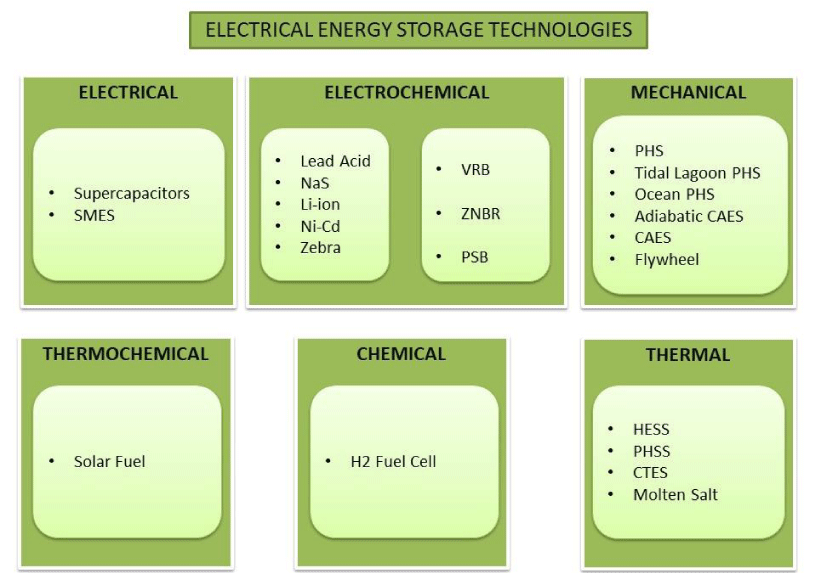
In most ESS, the electricity cannot be directly stored and for this reason is firstly converted to different forms and then can be converted back to electricity when this is necessary [11]. The numerous available energy storage technologies can be categorized into the following six groups [12] (Figure 1).
● Electrical: Supercapacitors [13-16], Superconducting Magnetic Energy Storage (SMES) [14,15,17].
● Electrochemical:
ο Secondary battery: Lead Acid battery [18,19], Sodium–Sulfur battery (NaS) [20-24], Lithium-ion (Li-ion) [25-27], Nickel–Cadmium battery (Ni-Cd) [28-30], Sodium–Nickel chloride battery (Zebra) [16,30,31].
ο Flow battery: Vanadium Redox Battery (VRB) [32-34], Zinc–Bromine (ZnBr) [16,35], Polysulfide bromine battery (PSB) [13,16,36,37].
● Mechanical: Pumped Hydro Storage (PHS) [15,17,38-43], Compressed Air Energy Storage [16,44,45], Adiabatic CAES [44-48], Flywheel [16,17,49,50].
● Thermal: Hydrogen Energy Storage Systems (HESS) [51-53], Pumped Heat Storage Systems (PHSS) [54-56], Cryogenic Thermal Energy Storage (CTES) [57,58], Molten Salt [16,59-62], for more information about thermal energy storage systems).
● Thermochemical: Solar fuel.
● Chemical: H2 Fuel cell.
In this study, ESS technologies that belong to thermochemical and chemical categories have not been examined.
Methodology
In this study, an assessment methodology of the available ESS will be employed to create the final bubble plot. This plot will facilitate the selection of the most appropriate storage technology for each scenario. The assessment methodology that this study is based on includes the techniques of Technology Readiness Levels, the Applicability Indicators under various constraints and lastly the determination of the uncertainty that is related to both previous techniques.
Technology readiness level
The TRL is an assessment tool that was initially created by NASA back in 1974 and since then it has been adopted by numerous organizations worldwide [63]. The typical TRL tool includes nine levels and each technology must cover a number of criteria to be categorized at a specific level. In our case, the main aim of the TRL process is to define the maturity level for every ESS that is examined in every scenario. For instance, a low TRL score for an ESS means that it is highly uncertain whether this technology is ready to be implemented or not.
It is necessary to ensure that the TRL tool contains a method to identify the uncertainty that is related to each ESS. The categorization of each technology to one of the nine available TRL levels is based on the information that can been found about that specific technology in the literature. However, every reference encompasses an uncertainty and according to this it can be classified in four categories: unreliable, poor, good and reliable. The best information will have the lowest uncertainty score. The bubble plots however, plot certainty (the inverse of uncertainty) as intuitively good score would be expected to have a bigger bubble. As it can be seen in Table 1 [64], reliable references (Category A) are considered the ones that have been peer reviewed, engineering textbooks that have a reputable publisher and thus a 20% uncertainty has been given to present how reliable is that reference. In the same way, information gathered from websites or self-published reports are unreliable and this is reflected to the 80% uncertainty.
The information for each attribute is collected by using many references which means that there is a need for an equation that can provide the total uncertainty:
where: is the number of references for category x and is the uncertainty of category x.
In Table 2 the TRL assessment of the Hydrogen ESS is depicted. Five references were used to gather information regarding the strengths and the weaknesses of this technology while three of them are categorized as type A and two of them as type B. The total normalized uncertainty is calculated as follows:
Applicability indicators
Applicability Indicators tool refers to the allocation of appropriate weightings to the most important attributes of each ESS. The attributes that can be seen in the next figure have been proposed in literature and reflect the critical performance factors of each storage technology. The weighting score that has been given is indicative and across different scenarios same attributes might have different weighting (Table 3).
The first two attributes, the power and the energy capacity, are the most crucial ones and for this reason they have a high weighting. A high score will be given to these attributes in case the power range is able to cover the capacity needs of the examined scenario.
The capital cost (‘CAPEX’) (£/kW) and the ‘LCOE’ (£/kWh) are of the same importance and indicate the most crucial financial aspects of each ESS. The capital and running costs of the combined cycle gas turbine have been used to provide a reference value for the financial attributes. The quantifiable targets are 1300 £/kWh for CAPEX and 0.8 £/kWh for LCOE [45]. To provide an accurate and up to date analysis the values regarding the CAPEX and LCOE that are found in literature have been transposed to GBP while the inflation rates have also been taken into consideration. The following table shows the final economic values that were chosen for a random storage technique. The same procedure was followed for all the chosen ESS (Table 4).
‘Response’ and ‘discharge time’ are important criteria as can be concluded from their weightings. For the ‘response’ attribute, the reference target value is set to be seconds-minutes while for the ‘discharge time’ attribute varies in every scenario. It is suggested that for ‘Efficiency’ and ‘daily self-discharge’ attributes 100% and 0 will be used as best possible targets.
The ‘cycle life’ and the ‘lifespan’ are both connected to the lifetime of a storage system and they also have a weighting. The target value for the ‘lifespan’ is 20 years and for the ‘cycle life’ is 7300, since it is proposed that the selected ESS will operate one full cycle during a day for these 20 years.
Environmental issues are reflected to the ‘environmental impact’ attribute which is very sensitive as it is usually affected by the local legislation which varies from one case study to another. The ‘additional needs’ criteria corresponds to the research issues or restrictions that might exist and need to be resolved.
A similar methodology, likewise for the TRL, to define the uncertainty of this process has been developed. All information about the attributes that is found in literature is classified in the corresponding category (e.g. ‘A’, ‘B, etc.). A normalized uncertainty will then be calculated by using the Eq.1 for each one of the 14 criteria and then the average of these uncertainties will indicate the total uncertainty. A ‘score’ column has been added to the Table 5 and contains the scores that each technology achieves in the specific attribute. The score of each attribute ranges from one to ten and it is an individual interpretation. Each score is then multiplied with the corresponding weight of each criteria and an overall score is obtained. After all the overall scores will be summed and then will be divided by 100 (which is the maximum overall score that can be achieved, in case that every attribute scores a 10) to reflect the total fractional score. In some cases, there is a need for alterations since it was not always possible to find information for a particular attribute. In that case that specific attribute is excluded from all the calculations.
All the above information can be validated by examining the Table 5. Starting with the ‘Normalized Uncertainty’ column we can verify the calculations of the ‘Capacity/Energy’ attribute:
The normalized uncertainty would be:
= 0.267 = 27%
By following the same procedure, we can obtain all the ‘Normalized Uncertainties’ and to calculate the ‘Total Uncertainty’ we simply find the average of them. Moving forward to the score section, the ‘efficiency’ attribute has been given a 0.7 weight and the score that was given for the expected efficiency (90%), found in literature, was 9. This score is multiplied by the weight and the weighted score (6.3) is obtained. The ‘Total technology score’, as was mentioned above, is the sum of all the available weighted scores. The ‘Fractional value’ is obtained by dividing the ‘Total technology score’ with the sum of the maximum possible weighted scores which is 91, since the maximum weighted score of the LCOE (10*0.9=9) attribute is missing.
Scenarios – Case Studies
Island grid with high renewable energy penetration
This scenario concerns an electric grid that is in islanded mode hence not connected to the central electricity grid. In this type of grids, the power needs were served solely by diesel generators but lately there is a growing transition to the renewable sources of energy. Nonetheless, electricity that is based in renewable energy has technical (e.g. power quality issues, intermittent nature of renewable sources of energy) and non-technical challenges (e.g. operating and maintenance) that need to be overcome. These challenges have been studied for many years now and have been well identified and presented in [65,66].
Agios Efstratios is a historic Greek island that is located in the Aegean Sea and recently the local authorities decided to implement a fossil-fuel independent profile. According to a realistic scenario it is feasible to achieve a load distribution for the renewable sources and the existing diesel generators of 66% and 34%, respectively. The grid’s information can be seen in the following table and it is proposed that the diesel generators will be used only as a back-up source (Table 6).
In Agios Efstratios the peak load demand occurs when there is almost zero generation from RES thus the ESS that will be selected needs cover the needs of the grid for 2-3 hours. The power capacity is selected to be 400 kW with an energy capacity of 1 MWh. It is proposed that the used ESS to be hydrogen even though this technology comes with a high cost and an overall moderate efficiency. The main reason for this is the long-term plan to operate hydrogen vehicles in the island [67].
The applicability indicators need to be weighted carefully and there must be an increasing weight on the ‘environmental impact’ attribute in the AI table. This is because there is an increasing environmental concern on that specific island as it has been recently characterized as the “green island” of Greece. Below it can be seen analytically how each indicator has been weighted for that specific scenario (Table 7).
Microgrid with high cooling load
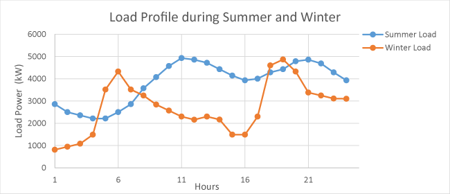
Microgrid defines a local group of loads and electric sources that usually are connected to a centralized grid but can also disconnect from it and operate autonomously if needed [68]. The case study that would be selected for that specific scenario it was necessary to have a high cooling load so the location of the microgrid should be in a tropical region or in an area close to it. The chosen microgrid is in the city of Hurghada in Egypt and all the data that will be presented are taken from actual values in that specific area [69] (Figure 2).
The high cooling load during summer can be clearly seen in the above graph, especially during the midday where the highest temperatures occur. The system is supplied by a diesel generator, a wind turbine, PV panels and an ESS that could support the smooth operation of the grid. It has been calculated, by taking into consideration the load profile, the wind speed spectrum and the solar irradiation data that the integrated ESS should have a power capacity of 4 MW and should be able to feed the grid for at least 3-4 hours. Analytically the power characteristics can be seen below:
The applicability indicators have been weighted separately for that case study. The power and the energy output have changed, the environmental impact weight can be decreased compared to the previous one and finally the discharge time needs to be higher than 4 hours (Tables 8,9).
Onshore wind farm
The case study that would be suitable for this scenario is the 58.5 MW wind farm in Wales at Cefn Croes. This wind farm has a successful operation for more than 12 years and lately it has been proposed that the integration of an ESS would increase the efficiency of the farm. Analytic data of the case study can be seen below (Table 10).
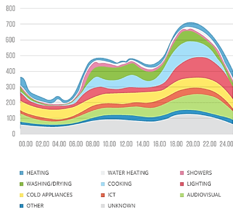
This wind farm is capable to provide energy for approximately 40,000 households in the surrounding area. It has been assumed that the load profile of each household is the one that can be seen in the figure. The y-axis corresponds to Power (W) and the x-axis to hours during a typical day. Each day it is estimated that there is 9.55 MW available for storage in the selected ESS for approximately 12 hours (Figure 3).
From the AI the ‘power rating’ attribute and the ‘capacity energy’ need to be adjusted to the needs of the current scenario. The ‘discharge time’ should be more than 12 hours which is quite a long time for most of the technologies (Table 11).
Offshore wind farm
The selected case study for the offshore wind farm is the future scenario of offshore wind capacity in UK. It is expected that by 2020 the installed offshore wind farms will have a total capacity of 40 GW [70,71]. It has been estimated that the maximum and minimum daily load demands in the UK grid is 51 GW and 29.5 GW respectively [72]. A 50% capacity factor for the offshore wind farm is assumed which under a simplistic method means that the wind turbines feed the grid with 40 GW for 12 hours over a daytime period [73]. With the use of the average minimum load demand and the 40 GW from the wind generation it can be concluded that 10.5 GW is available to be stored for the period of 12 hours daily. Consequently, the 10.5 GW for 12 hours means that the energy capacity required for the ESS is approximately 126 GWh. The 40 GW of offshore wind farms will be distributed in the 34 wind farms across the UK which indicated that the average capacity of each ESS in the corresponding wind farm will be 3706 MWh with a power capacity of 309 MW.
The applicability indicators are presented in the table below and the adjustment in the ‘power rating’ and in the ‘energy capacity’ are presented. Similarly to previous scenario the selected ESS needs to be charged unstoppably for 12 hours (Table 12).
Solar system
PV arrays can be considered for different kinds of applications, from small standalone to large scale solar power plants [74]. Many areas in Australia have very high average solar irradiation and are very suitable for solar panels installation and for this scenario the case study of Rockhampton, a subtropical area in Queensland, has been selected. The scenario includes a standalone PV system installed on a residential house and it is examined how an ESS could increase the integration of the PV array hence the saving of money (Table 13).
The model that has been simulated includes a 10 kW PV, a 1 kW diesel generator and storage capacity of 69.12 kWh. The simulation shows that the ESS that will be integrated in that case study should be able to store approximately 4 MWh/yr. The diesel generator was almost not used at all as the main role of it was to be a back-up. It needs to be mentioned specifically in that scenario the integration of storage improves significantly the PV production.
The adjustments in the applicability indicators can be seen in the following table. Extra weight was assumed in the cycle life indicator. This is because the total cost of the whole system is directly paid from the household which means that there is an additional need to maintain the system in the highest standards for the longest possible period in order to save more money (Table 14).
Assessment of Results
After the assessment methodology was completed for each one of the case studies, a matrix that contains all the results was created. The first column of the table contains the proposed ESS while the following columns have the AI and TRL scores accompanied by the calculated uncertainty. The ‘Normalized Uncertainty’ tab reflects the average level of uncertainty related to each technology. This matrix was used to create the bubble plot of the corresponding case study. The appendix section includes the analytic presentation of the AI and TRL tool as well as the references that have been used for each ESS (Appendix A).
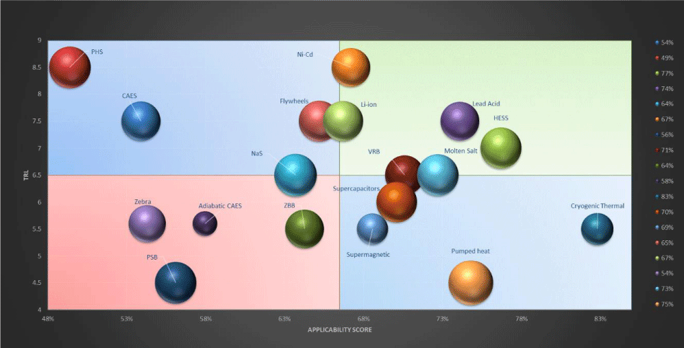
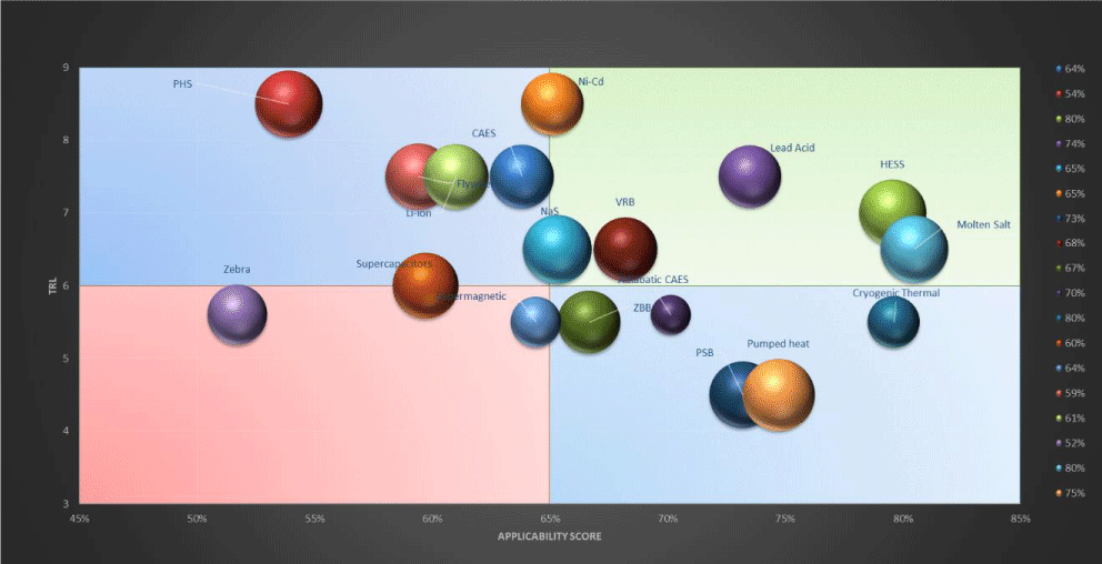
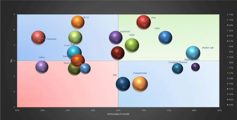
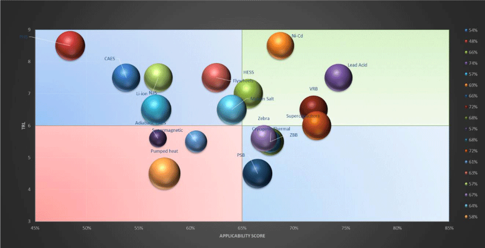
The TRL score is on the y-axis while the AI score is on the x-axis and the bounds of each axis were chosen in a way that offers a better visual understanding of the plot. It needs to be mentioned that the size of the bubbles is inversely proportional to the level of uncertainty which can be seen on the matrix with the assessment results. In other words, the smaller the size of the bubble is the bigger the uncertainty of this technology. The plot has been divided into four quadrants to indicate the location of the most promising ESS for that case study. The top right quadrant contains the ESS that have high TRL and AI score hence are the most appropriate for this scenario while the ESS on the bottom left quadrant have low TRL and AI score and are probably not suitable. The other two quadrants contain ESS that either are suitable for that case study but are not commercialized (bottom right quadrant) or well-developed technologies that achieve a low AI score (top left quadrant). It is expected that in each scenario there will be a transition of each technology only on the x-axis which is the AI axis and not on the y-axis since the TRL factor remains the same in every case study.
Agios efstratios case study
Figure 4 and Table B1 in Appendix B contain the results of the simulation regarding the islanded grid. Despite the fact that PHS and CAES are the most developed and commercialized ESS, they do not seem to be a promising solution for this case study. The needed storage capacity of the island is 400 kW while these technologies are mainly used in utility and large-scale power plants and they are not cost-effective if used in small scale applications like this. Α good AI score was achieved by Ni-Cd and Li-ion batteries and in combination with the relative high TRL they are considered to be a viable solution for this scenario. Α noticeable category of ESS is the one that includes HESS, Molten Salt and VRB flow batteries. This branch of technologies has achieved a high applicability score which means that they could be suitable alternative for storage. However, their TRL score indicates that they are not well established yet or that further research is needed. An interesting observation in the plot is the overall score of the Cryogenic Thermal ESS which has achieved that highest AI score (83%) but its TRL score is below the average. CTES has a minimum environmental impact, it is scalable and suitable for the required power capacity range of this case study, but it is still not proven in full scale and there is a lot of ongoing research regarding the heat losses in pipes (Table 15).
Microgrid in egypt case study
The results of the microgrid scenario in Egypt can be seen in the Figure 5 and Table B2 in Appendix B. The ESS that achieved the highest scores are the HESS, the Molten salt and the Cryogenic thermal storage. From this branch of technologies, HESS also has the highest TRL (7.0) and has also higher AI compared to previous case study. PSB storage system has a noticeable increase in the AI score, from 56% to 73% but remains a non-reliable technology since it achieves the lowest TRL score (4.5). PHES and CAES technologies present a higher AI score due to the higher power capacity needed for this case study. However, they are still located in the top left quadrant which means that they do not achieve the required AI for this scenario. VRB and NaS batteries are on the boundaries of the top right quadrant and it is expected that in the next years these two technologies will be more commercialized hence will provide a solid solution for microgrid storage. As was expected for the Electrical ESS, the higher power capacity needed for the scenario the lower AI score they will achieve. Indeed, Supercapacitors and Supermagnetic technologies present a decrease in their AI score and they are on the bottom left quadrant. Another interesting fact in these two case studies is that Adiabatic CAES achieves higher AI score than the conventional CAES but in general there is still a lot of ongoing research and a lack of extensive data sets for comparison.
Onshore wind farm
The results of the onshore wind farm scenario can be seen in the Figure 6 and Table B3 in Appendix B. As the power capacity needs of the proposed case study are increased it is expected that PHES and CAES technologies will be moving on the right direction of the x-axis, closer to the top right quadrant. Indeed, onshore and much more offshore wind farms have larger power capacities demand and these two technologies become more suitable. In this scenario HESS achieves again a reasonably high AI score and compared to its TRL score seems to offer the best storage solution for this scenario. Pumped heat is a technology with favorable characteristics and seems to be suitable for the most scenarios mainly due to its high volumetric energy density. However, it is still under development and this is reflected to its very low TRL score which is way below the average. Li-ion batteries on the other side, they have a quite high TRL score since this technology has been well established and tested in various applications. Nonetheless, only lately battery ESS are gradually integrated in large scale power systems and thus there are no solid results yet. The most famous recent battery ESS is probably the 129 MWh battery system in Hornsdale, that has been announced by Tesla company [74]. Zebra batteries are again not suitable storage technology for this case mainly because its relatively small power-range and its AI is reasonable only in case studies with small power needs.
Offshore wind farm
The results of the offshore wind farm scenario can be seen in the Figure 7 and Table B4 in Appendix B. PHS and CAES systems are the most suitable for storage in future offshore wind farms in UK. Their power and energy range can fully cover the needs of this scenario and these two technologies have been applied on large scale power systems. Adiabatic CAES achieves the highest AI score but its low TRL score does not allow it to be considered as a suitable storage for that application. In this scenario, the power demand of the storage systems has been raised significantly and for this reason most technologies have been moved to the left-direction of the x-axis. So, when it comes to large scale systems, it is obvious that only PHES and CAES along with HESS can offer a reliable storage solution. Molten salt is also an interesting ESS but in real life applications this technology should mainly be coupled with solar power plants. This is the first case study where the Lead-acid batteries are out of the top right quadrant because their power range is not suitable to cover the needs of a large-scale power systems.
Solar power system case study
The results of the solar power system case study can be seen in the Figure 8 and Table B5 in Appendix B. From all the studied scenarios, this case study is the most special because the proposed storage systems would be installed on a rooftop of a residential building. Ni-Cd, Lead-acid batteries and the HESS would offer the most reliable solution for this scenario. Flywheel storage system and Zebra batteries present a great increase in their AI mainly because the power needs of this scenario are low. VRB technology is on the boundaries of the top right and bottom right quadrant which means that in future it is expected to achieve a higher TRL score and to become a good storage alternative. Same expectations also exist for the supercapacitors however their use is currently restricted in the electrified means of transport. PHS and both CAES storage systems are not suitable for this application. Although recently there is an ongoing development of small scale Pumped Hydro and CAES that could be integrated in buildings [75]. A common conclusion is that Pumped Heat and PSB storage need a lot of research to achieve higher TRL levels and thus to be considered more suitable for more case studies.
Conclusions
The proposed Energy Storage Systems that would be integrated in each one of the case studies had to be assessed in terms of suitability and maturity. The assessment methodology that has been applied in this study includes the Technology Readiness Level and Applicability Indicator tools. Both tools were employed in order to produce a 3-D bubble plot that would facilitate the selection of the most appropriate ESS for every examined scenario. The identification of the basic requirements, such as the power and energy capacity needs, of the power system in each case study was a basic step.
Based on the final bubble plots for each one of the scenarios, in each scenario there are different ESS that dominate and fail to impress as this is depicted in bubble plot. In fact, mechanical storage technologies seem to be suitable for large scale systems due to their relative high capital cost and power range. PHS and CAES systems are the most well-known mechanical ESS with high TRL score achieved a high AI only in the case studies were the power needs were more than 10 MW (e.g. onshore-offshore wind farm). Adiabatic CAES is a technology that presents interesting results as it has achieved high applicability scores in most scenarios. However, its low TRL score indicates that this technology cannot be currently employed as there is a lot of ongoing research. Adiabatic CAES belongs to a branch of technologies that have favorable characteristics but low level of maturity. This branch includes also all the Thermal storage technologies except Hydrogen storage. Indeed, bubble plots prove that Cryogenic Thermal, Molten Salt and Pumped Heat storage have achieved a high applicability score in all the case studies and they seem to be a promising solution for the near future. Among them, Molten salt is most possible to be employed soon as it has an average TRL level and Pumped Heat is the least possible since it is still under development. On the other hand, Hydrogen Storage seems to be one of the most suitable storage solutions for all the case studies as it has been in the top right quadrant in all the scenarios. Hydrogen is a versatile storage option and is lately tested in utility scale systems. In addition, hydrogen vessels are also expected to be available soon. From the Electrochemical storage category, Lead Acid batteries have a remarkable applicability score as well as a high TRL indicator as there is an extensive industrial and commercial experience of this low-cost technology. Nonetheless it has not been proven yet in large scale systems and for this reason in the offshore wind farm scenario achieved a relatively low score. Vanadium Redox flow and NaS batteries present a moderate TRL score of 6.5 and for this reason they are located on the boundary section of upper and lower quadrants. Their relative high applicability score shows that in future if the safety concerns will be resolved these two technologies might be a robust storage technology. Lithium-ion batteries is one of the most commercialized ESS since for many years it has been used in small and micro scale power systems and for two decades it is being used exclusively in all mobile phones. For this reason, it has a very high TRL score but only lately it is employed in utility scale grids and there is not sufficient feedback yet. Lastly, both Supercapacitors and Superconducting magnetic storage technology that belong to Electrical ESS present identical results. In small scale systems, such as the island grid and residential solar power system, seem to be a good storage solution but when it comes to higher power needs these technologies may not be applied. Supercapacitors are widely used in electric vehicles while large scale superconducting magnetic storage plants have not yet tested in real life applications.
- Evans A, Strezov V, Evans T (2012) Assessment of utility energy storage options for increased renewable energy penetration. Renewable Sustainable Energy Review 16: 4141-4147. Link: https://tinyurl.com/y3p9de23
- Capellán-Pérez I, Mediavilla M, de Castro C, Carpintero Ó, Miguel L (2014) Fossil fuel depletion and socio-economic scenarios: An integrated approach. Energy 77: 641-666. Link: https://tinyurl.com/y6gv928t
- Kefford B, Ballinger B, Schmeda-Lopez D, Greig C, Smart S (2018) The early retirement challenge for fossil fuel power plants in deep decarbonisation scenarios. Energy Policy 119: 294-306. Link: https://tinyurl.com/yyegwlwh
- Amusat O, Shearing P, Fraga E (2018) Optimal design of hybrid energy systems incorporating stochastic renewable resources fluctuations. J Energy Storage 15: 379-399. Link: https://tinyurl.com/y45vzjea
- Guney M, Tepe Y (2017) Classification and assessment of energy storage systems. Renewable Sustainable Energy Review 75: 1187-1197. Link: https://tinyurl.com/y28l7zmn
- Sabihuddin S, Kiprakis A, Mueller M (2014) A Numerical and Graphical Review of Energy Storage Technologies. Energies 8: 172-216. Link: https://tinyurl.com/yymdclyv
- Khodayari M, Aslani A (2018) Analysis of the energy storage technology using Hype Cycle approach. Sustainable Energy Technologies Assessment 25: 60-74. Link: https://tinyurl.com/yy24wa4g
- Luo X, Wang J, Dooner M, Clarke J (2015) Overview of current development in electrical energy storage technologies and the application potential in power system operation. Applied Energy 137: 511-536. Link: https://tinyurl.com/y5eg343o
- Chen H, Cong T, Yang W, Tan C, Li Y, et al. (2009) Progress in electrical energy storage system: A critical review. Progress Natural Science 19: 291-312. Link: https://tinyurl.com/y5ds45zs
- Roberts B, Sandberg C (2011) The Role of Energy Storage in Development of Smart Grids. Proceedings of the IEEE 99: 1139-1144. Link: https://tinyurl.com/yyd7jfth
- Das C, Bass O, Kothapalli G, Mahmoud T, Habibi D (2018) Overview of energy storage systems in distribution networks: Placement, sizing, operation, and power quality. Renewable Sustainable Energy Review 91: 1205-1230. Link: https://tinyurl.com/y29u8tk3
- Luo X, Wang J, Dooner M, Clarke J (2015) Overview of current development in electrical energy storage technologies and the application potential in power system operation. Applied Energy 137: 511-536. Link: https://tinyurl.com/y5eg343o
- Guney M, Tepe Y (2017) Classification and assessment of energy storage systems. Renewable Sustainable Energy Review 75: 1187-1197. Link: https://tinyurl.com/y28l7zmn
- Sundararagavan S, Baker E (2012) Evaluating energy storage technologies for wind power integration. Solar Energy 86: 2707-2717. Link: https://tinyurl.com/y453hz4z
- Beaudin M, Zareipour H, Schellenberglabe A, Rosehart W (2010) Energy storage for mitigating the variability of renewable electricity sources: An updated review. Energy Sustainable Development 14: 302-314. Link: https://tinyurl.com/yy2d56ph
- Medina P, Bizuayehu A, Contreras J (2014) Electrical Energy Storage Systems: Technologies’ State-of-the-Art, Techno-Economic Benefits and Applications Analysis. Hawaii International Conference on System Science. Link: https://tinyurl.com/y29cqko8
- Díaz-González F, Sumper A, Gomis-Bellmunt O, Villafáfila-Robles R (2012) A review of energy storage technologies for wind power applications. Renewable Sustainable Energy Review 16: 2154-2171. Link: https://tinyurl.com/y2ceut3b
- Zhang C, Wei Y, Cao P, Lin M (2018) Energy storage system: Current studies on batteries and power condition system. Renewable Sustainable Energy Review 82: 3091-3106. Link: https://tinyurl.com/y2voaspd
- May G, Davidson A, Monahov B (2018) Lead batteries for utility energy storage: A review. J Energy Storage 15: 145-157. Link: https://tinyurl.com/yxtfdt96
- Kumar D, Rajouria S, Kuhar S, Kanchan D (2017) Progress and prospects of sodium-sulfur batteries: A review. Solid State Ionics 312: 8-16. Link: https://tinyurl.com/y5mum2d7
- Atherton J, Sharma R, Salgado J (2017) Techno-economic analysis of energy storage systems for application in wind farms. Energy 135: 540- 552. Link: https://tinyurl.com/y43quhc9
- Min J, Lee C (2012) Numerical study on the thermal management system of a molten sodium-sulfur battery module. J Power Source 210: 101-109. Link: https://tinyurl.com/y3bbv8lg
- Shen X, Liu H, Cheng X, Yan C, Huang J (2017) Beyond lithium ion batteries: Higher energy density battery systems based on lithium metal anodes. Energy Storage Materials 12: 161-175. Link: https://tinyurl.com/y5uemz57
- Sabihuddin S, Kiprakis A, Mueller M (2014) A Numerical and Graphical Review of Energy Storage Technologies. Energies 8: 172-216. Link: https://tinyurl.com/yymdclyv
- Jaiswal A (2017) Lithium-ion battery based renewable energy solution for off-grid electricity: A techno-economic analysis. Renewable Sustainable Energy Review 72: 922-934. Link: https://tinyurl.com/y49gqta7
- Paul Ayeng'o S, Schirmer T, Kairies K, Axelsen H, Uwe Sauer D (2018) Comparison of off-grid power supply systems using lead-acid and lithium-ion batteries. Solar Energy 162: 140-152. Link: https://tinyurl.com/yyuhrdcy
- Cho J, Jeong S, Kim Y (2015) Commercial and research battery technologies for electrical energy storage applications. Prog Energy Combust Sci 48: 84-101. Link: https://tinyurl.com/y26bgo28
- Akbari H, Browne M, Ortega A, Huang M, Hewitt N, et al. (2018) Efficient energy storage technologies for photovoltaic systems. Solar Energy.
- Opiyo N (2016) Energy storage systems for PV-based communal grids. J Energy Storage 7: 1-12. Link: https://tinyurl.com/y5z4kflz
- Dunn B, Kamath H, Tarascon J (2011) Electrical Energy Storage for the Grid: A Battery of Choices. Science 334: 928-935. Link: https://tinyurl.com/y4zg7so4
- Ellis B, Nazar L (2012) Sodium and sodium-ion energy storage batteries. Curr Opin Solid State Mater Sci 16: 168-177. Link: https://tinyurl.com/y49hubux
- Bhattacharjee A, Saha H (2017) Design and experimental validation of a generalised electrical equivalent model of Vanadium Redox Flow Battery for interfacing with renewable energy sources. J Energy Storage 13: 220-232. Link: https://tinyurl.com/yxuny8zl
- Alotto P, Guarnieri M, Moro F (2014) Redox flow batteries for the storage of renewable energy: A review. Renewable Sustainable Energy Review 29: 325-335. Link: https://tinyurl.com/yyd2tfjm
- Fathima A, Palanismay K (2017) Modeling and Operation of a Vanadium Redox Flow Battery for PV Applications. Energy Procedia 117: 607-614. Link: https://tinyurl.com/y3g7wb3t
- Wu M, Zhao T, Wei L, Jiang H, Zhang R (2018) Improved electrolyte for zinc-bromine flow batteries. J Power Sources 384: 232-239. Link: https://tinyurl.com/y3szn9pr
- Zhao P, Zhang H, Zhou H, Yi B (20050 Nickel foam and carbon felt applications for sodium polysulfide/bromine redox flow battery electrodes. Electrochim Acta 51: 1091-1098. Link: https://tinyurl.com/yycpnufr
- Lim T, Menictas C, Skyllas-Kazacos M (2015) Advances in batteries for medium- and large-scale energy storage. Cambridge, UK: Woodhead Publishing. Link: https://tinyurl.com/y46ke9lr
- Huggins R (2016) Energy Storage. Cham [etc.]. Springer 1-12.
- Foley A, Leahy P, Li K, McKeogh E, Morrison A (2015) A long-term analysis of pumped hydro storage to firm wind power. Applied Energy 137: 638-648. Link: https://tinyurl.com/y525fqqm
- Kocaman A, Modi V (2017) Value of pumped hydro storage in a hybrid energy generation and allocation system. Applied Energy 205: 1202-1215. Link: https://tinyurl.com/yy9a5hcf
- Stocks M (2016) Pumped Hydro Energy Storage to support a 50-100% renewable electricity grid. PhD. The Australian National University, 2016. Link: https://tinyurl.com/y2zdmxrj
- Rehman S, Al-Hadhrami L, Alam M (2015) Pumped hydro energy storage system: A technological review. Renewable Sustainable Energy Review 44: 586-598. Link: https://tinyurl.com/y5xdzl66
- Deane J, Ó Gallachóir B, McKeogh E (2010) Techno-economic review of existing and new pumped hydro energy storage plant. Renewable Sustainable Energy Review 14: 1293-1302. Link: https://tinyurl.com/y3wednnp
- Budt M, Wolf D, Span R, Yan J (2016) A review on compressed air energy storage: Basic principles, past milestones and recent developments. Applied Energy 170: 250-268. Link: https://tinyurl.com/y3q9yocq
- Lazard's Levelised Cost of Storage Analysis (2017) 3rd ed. [ebook] Lazard. Link: https://tinyurl.com/y4luxu2e
- Dreißigacker V (2017) Power-to-heat in adiabatic compressed air energy storage power plants for cost reduction and increased [30]. Flywheel energy storage systemflexibility. Heat and Mass Transfer 54: 955-962. Link: https://tinyurl.com/y2teo4za
- Tola V, Meloni V, Spadaccini F, Cau G (2017) Performance assessment of Adiabatic Compressed Air Energy Storage (A-CAES) power plants integrated with packed-bed thermocline storage systems. Energy Conversion Management 151: 343-356. Link: https://tinyurl.com/y2ln6laz
- Sciacovelli A, Li Y, Chen H, Wu Y, Wang J, et al. (2017) Dynamic simulation of Adiabatic Compressed Air Energy Storage (A-CAES) plant with integrated thermal storage – Link between components performance and plant performance. Applied Energy 185: 16-28. Link: https://tinyurl.com/y4wnbnjl
- Mousavi GS, Faraji F, Majazi A, Al-Haddad K (2017) A comprehensive review of Flywheel Energy Storage System technology. Renewable Sustainable Energy Review 67: 477-490. Link: https://tinyurl.com/yyjnxbwf
- Sebastián R, Peña Alzola R (2012) Flywheel energy storage systems: Review and simulation for an isolated wind power system. Renewable Sustainable Energy Review 16: 6803-6813. Link: https://tinyurl.com/yysxwpzt
- Ganeshan A, Holmes D, Meegahapola L, McGrath B (2017) Enhanced Control of a Hydrogen Energy Storage System in a Microgrid. IEEE. Link: https://tinyurl.com/y44lx3zj
- Zhang F, Zhao P, Niu M, Maddy J (2016) The survey of key technologies in hydrogen energy storage. Int J Hydrogen Energy 41: 14535-14552. Link: https://tinyurl.com/yycglrvp
- Sreedhar I, Kamani K, Kamani B, Reddy B, Venugopal A (2018) A Bird's Eye view on process and engineering aspects of hydrogen storage. Renewable Sustainable Energy Review 91: 838-860. Link: https://tinyurl.com/y2gzg8jm
- Roskosch D, Atakan B (2017) Pumped heat electricity storage: potential analysis and orc requirements. Energy Procedia 129: 1026-1033. Link: https://tinyurl.com/yyetbn8f
- Smallbone A, Jülch V, Wardle R, Roskilly A (2017) Levelised Cost of Storage for Pumped Heat Energy Storage in comparison with other energy storage technologies. Energy Conversion Management 152: 221-228. Link: https://tinyurl.com/y5kx6x5y
- Benato A, Stoppato A (2018) Pumped Thermal Electricity Storage: A technology overview. Ther Science and Engineering Progress 6: 301-315. Link: https://tinyurl.com/y5vnzsj9
- Hamdy S, Morosuk T, Tsatsaronis G (2017) Cryogenics-based energy storage: Evaluation of cold exergy recovery cycles. Energy 138: 1069-1080. Link: https://tinyurl.com/y64wz9n9
- Abdo R, Pedro H, Koury R, Machado L, Coimbra C, et al. (2015) Performance evaluation of various cryogenic energy storage systems. Energy 90: 1024-1032. Link: https://tinyurl.com/yybs2nme
- Evans A, Strezov V, Evans T (2012) Assessment of utility energy storage options for increased renewable energy penetration. Renewable Sustainable Energy Review 16: 4141-4147. Link: https://tinyurl.com/y3q5tq48
- Alva G, Lin Y, Fang G (2018) An overview of thermal energy storage systems. Energy 144: 341-378. Link: https://tinyurl.com/yy29e3kk
- Fernandes D, Pitie F, Caceres G, Baeyens J (2012) Thermal energy storage. How previous findings determine current research priorities. Energy 39: 246-257. Link: https://tinyurl.com/y4rh2d5y
- Zhang H, Baeyens J, Caceres G, Degreve J, Lv Y (2016) Thermal energy storage: Recent developments and practical aspects. Prog Energy Combust Sci 53: 1-40. Link: https://tinyurl.com/y6zxjso6
- Straub J (2015) In search of technology readiness level (TRL) 10. Aerosp Sci Technol 46: 312-320. Link: https://tinyurl.com/y6rfcppn
- Paterson J (2012) Wind Energy Storage Technologies with a view to offshore generation. M.Eng. University of Aberdeen.
- Enslin JHR (2010) Network impacts of high penetration of photovoltaic solar power systems. IEEE PES General Meeting, Providence, RI 1-5.
- Byrnes L, Brown C, Wagner L, Foster J (2016) Reviewing the viability of renewable energy in community electrification: The case of remote Western Australian communities. Renewable Sustainable Energy Review 59: 470-481. Link: https://tinyurl.com/y5ndplsz
- Kyriakidis I, Braun P, Chaudhary S (2012) Effect of Energy Storage in Increasing the Penetration of RES in the Remote Island of Agios Efstratios. 3rd IEEE International Symposium on Power Electronics for Distributed Generation Systems (PEDG). IEEE Press 814-819. Link: https://tinyurl.com/y4tly2jp
- Hirsch A, Parag Y, Guerrero J (2018) Microgrids: A review of technologies, key drivers, and outstanding issues. Renewable Sustainable Energy Review 90: 402-411. Link: https://tinyurl.com/y4drbvzt
- Beshr E, Abdelghany H, Eteiba M (2018) Novel optimization technique of isolated microgrid with hydrogen energy storage. PLOS ONE 13: e0193224. Link: https://tinyurl.com/y3zgpkns
- Renewable UK (2012) 10 facts about UK offshore wind.
- Ovoenergy.com (2018) How much electricity does a home use? OVO Energy. Link: https://tinyurl.com/hycfeb5
- Public Interest Research Centre on behalf of The Offshore Valuation Group (2010) The Offshore Valuation: A valuation of the UK’s offshore renewable energy resource. 28-29. Link: https://tinyurl.com/y4xjxok2
- Arif M, Oo A, Ali A, Shafiullah G (2013) Significance of Storage on Solar Photovoltaic System-A Residential Load Case Study in Australia. Smart Grid Renewable Energy 04: 167-180. Link: https://tinyurl.com/y49hb8e6
- Ayre J, Ayre J (2018) Tesla Completes World's Largest Li-ion Battery (129 MWh) In South Australia, Clean Technica. Link: https://tinyurl.com/y5rbl87m
- de Oliveira e Silva G, Hendrick P (2016) Pumped hydro energy storage in buildings. Applied Energy 179: 1242-1250. Link: https://tinyurl.com/y5r7lv9y
Article Alerts
Subscribe to our articles alerts and stay tuned.
 This work is licensed under a Creative Commons Attribution 4.0 International License.

 Save to Mendeley
