Annals of Environmental Science and Toxicology
Applying a novel generalized model of sedimentation to the design of settlers and thickeners: Integration and extension of the classical procedures
JL Bueno-de-las-Heras*, A Gutiérrez-Lavín and MM Mahamud-López
Cite this as
Bueno-de-las-Heras JL, Gutiérrez-Lavín A, Mahamud-López MM (2024) Applying a novel generalized model of sedimentation to the design of settlers and thickeners: Integration and extension of the classical procedures. Ann Environ Sci Toxicol 8(1): 043-056. DOI: 10.17352/aest.000078Copyright
© 2024 Bueno-de-las-Heras JL, et al. This is an open-access article distributed under the terms of the Creative Commons Attribution License, which permits unrestricted use, distribution, and reproduction in any medium, provided the original author and source are credited.A new generalized procedure previously introduced and justified by the authors, based on the simultaneous integration of the macroscopic and microscopic differential mass balances by introducing the concept of separation units as an extension of the transfer unit concept was applied here to sedimentation. This similarity leads to a broader analogy with basic transfer and transformation unit operations, at this step focused on the formulation and contrast of a generalized form of the so-called design or sizing equation. This model is comparatively applied under restricted flow Conditions-Vertical Flow Settlers (CSTS) - with the classical methods and extended to the design of horizontal flow settlers (PFS). That opens the door to the sizing of settlers and thickeners in the presence of deviations from these ideal flow models and with other operating configurations. Such a contribution to a desirable generalization and homologation is according to Chemical Engineering methodology specifically in the frequently empirical or casuistic treatment of unit operations with particulate solids.
Abbreviations
Symbols: When introduced or defined, their casuistic dimensions and particularities are described in the text.
A: In general, gateway, open door, or collector: appropriate descriptor of the relevant spatial dimension in transference or separation, in general, surface area or volume
AS, ASTM, ASCC, AKY: Effective surface for separation by sedimentation according to different methods [=]L2
Au: Unit area: Specific surface area according to Talmadge and Fitch
ASU: Surface area of separation (or sedimentation) unit/unit of separation [=]L2
BS: Batch settler
c, cp: Particle mass concentration [=]ML-3
CSTS: Continuous Stabilized Tank Settler
Ɛ: Porosity [=] dimensionless (dl)
F: Mathematical function relating settling rate vp to concentration cp
φ: Solids volumetric fraction [=] dimensionless (dl)
M: Mass [=]M
N: Potential exponent, some form of dimensionless mechanism/order indicator
NSU: Number of /separation (or sedimentation) units/ units of separation [=]dl
PFS: Plug Flow Settler
RTD: Residence time distribution
S, Sp: Flow density of particles [=]ML-2t-1
SI: Intrinsic mass flow density of particles (S, Sp) by bulk sedimentation [=]ML-2t-1
SII: Mass flow density of particles by entrainment [=]ML-2t-1
ST: Global or bulk flow density of particles [=]ML-2t-1
T: Time [=]t
t’: Hypothetical settling time corresponding to an ancillary coordinate Z’[=]t
TSU: Time of the separation (or sedimentation) unit/unit of separation [=]t
u: Rate of ascensional propagation of discontinuities or gradients in non-stationary regime [=]Lt-1
v: Relative flow rate [=]Lt-1
V: Volume of any system [=]L3
vp: Settling rate of individualized particles of certain hydrodynamic dimensions [=]Lt-1
vs: Hindered settling rate of a suspension of certain concentration [=]Lt-1
W,W: Mass or volumetric flow [=]Mt-1, L3t-1,
x,y,z: Orthogonal coordinates [=]L
z,Z: Vertical coordinate, height of the suspension in a settler [=]L
z’,Z’: Hypothetical coordinate: Theoretical initial level of a homogeneous synchronous settling suspension of concentration cpo =cpj , [=]L
Introduction
Antecedents
Sedimentation, an apparently simple omnipresent phenomenon, is the core of a hydraulic solid-fluid separation operation in which particles, denser than the continuous medium, settle owing to the gravity force. Sedimentation, in its different variants, is a unit operation widely used in industrial processes involving the handling of macrofluids (particularly mixing, classification, and separation) due to its operational simplicity, and low energetic consumption, mainly when high flow rates are to be processed [1].
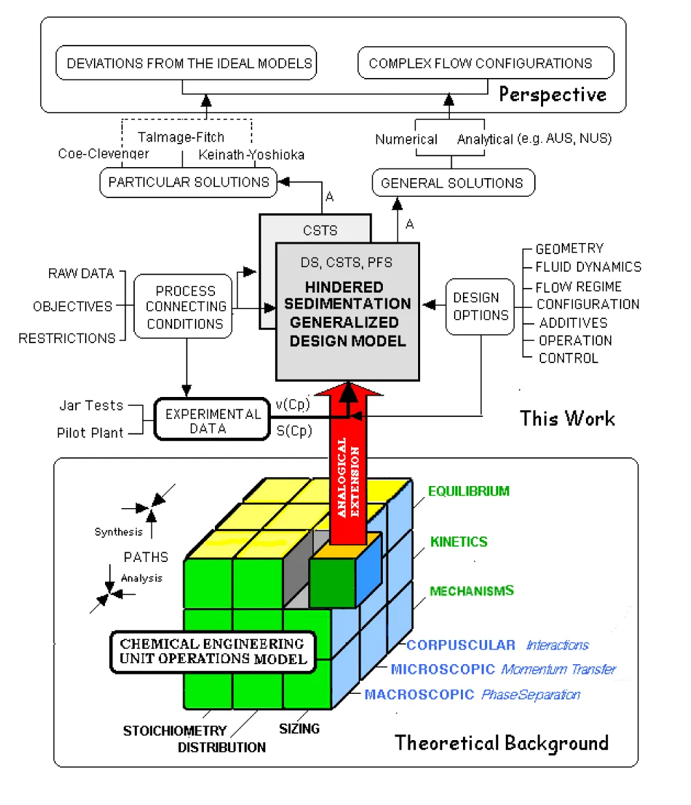
The study of sedimentation as a separation and classification tool used and referred to since time immemorial has undergone an evolution very similar to that of the study of basic fluid-mechanical operations with solids, an evolution that, in turn, has been passing -on another time scale - with the conceptual and methodological evolution of Chemical Engineering itself [2-7]: Firstly, a stage may be identified in the practice of solid-fluid separations that in the Pierre Le Goff [8] compilation could be identified as “Rustic Engineering”, followed by- second stage, “Technical Chemistry” or “Industrial Chemistry”- the macroscopic systematization of unit operations typical of encyclopedic and initiation books like Brown [9] in the field of process industries, and manuals like Degrémont [10], e.g., when it comes to its application in water treatment (where Sedimentation is omnipresent). Thirdly, a tendency towards microscopic systematization and fitting of these operations into the methodological corpus of Chemical Engineering can be identified, with the conceptual framework used in the integrated treatment of Transformation and Transport Phenomena in the Unit Operations model (see Graphical Abstract) according to the scientific gnoseological coherence state “Categorical Closure” [11]. This is the gateway to the application of the resources of dynamics, simulation, and control in a unitary way to all kinds of transfer and/or transformation Unit Operations.
Context
Despite the extensive use of sedimentation throughout history, the modelling of this process is far from being clearly defined, in contrast to other basic or unit operations of the Chemical Engineering processes. Sedimentation is a separating operation based on apparently simple and supposedly well-known principles [12]. Perhaps more than other hydraulic separation operations, sedimentation has had a comparatively very modest methodological treatment, which has contributed to feeding the intuitive conviction that this is a highly empirical operation, whose design rests more on heuristic principles and generous oversizing than on rigorous and reliable formulations. However, the study of sedimentation has undergone a significant increase in recent years as a result of the awareness of environmental issues and successive collateral impulses, due to the boom in residual effluent treatment technologies at the beginning of the Seventies and, more recently, with the resurgence of classical technologies, re-explored thanks to the use of new instrumental techniques and the availability of versatile means of calculation, simulation, and control [13-15] Sedimentation now appears as an operation susceptible to a rigorous analog modeling with respect to other transport operations, which represents the foundation for an adequate control of operation [15,16]. Gravity sedimentation is undoubtedly a very efficient separation process that requires affordable technology, and low maintenance and works with a sustainable, for the time being, tax-free energy source.
Theory
Background: Mechanism underlying kinetics, equilibrium and stoichiometry
In fact, there are two convergent routes to establish a massive sedimentation model (at the macroscopic level of description) useful in sedimentation design: Theoretical or inductive and empirical or deductive. The former tries to justify any formulation of the resulting settling rate as a consequence of the integration of successive corrections of the microscopic Stokes, Stokes–Einstein, Hawksley, or Newton individualized models, with an increasing significance of concentration in interactions (slowdown and uniformization). The latter starts by accepting uniformity (hindered or bulk settling) and tries to justify it. This is the case of the initial Kynch [17] mathematical model (theoretically limited to undeformable and identical spherical particles), which establishes (Fitch [18,19], Sangkyum [16], Tiller [20], Obata-Watanabe [21]) that the bulk sedimentation rate of a suspension of certain characteristics (usually evaluable by the evolution of the sediment front as vpi = -dzi/dt, from jar-tests) is a decreasing function fs of the concentration of solids cp under any of its forms of expression, mass concentration or volumetric fraction, φ = 1-ε.
From that, it follows that the mass flow density, whose dimensions are ML-2t-1, can be defined and written as:
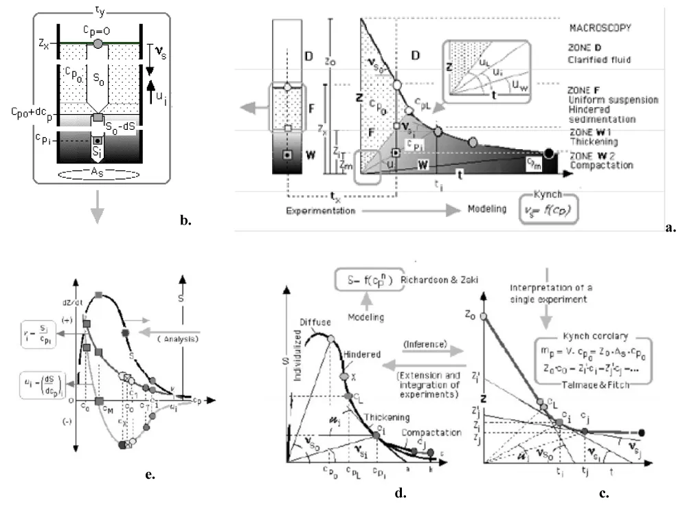
This property is experimentally determinable [22] or deducible from theory [16,23] as a biased bell-shaped function S(cp) tending to null values of the ordinate both to infinite dispersion (zero concentration) and to concentrations close to the sediment compaction. This kinetic function (kinetic curve in graphic terms, see Figure 1, that interrelates and summarizes the basic concepts involved in the analysis and modelling of this operation) is conceptually similar to those for flow density in the mass transfer or chemical reaction: simultaneously contains the concept and physical sense of ‘state function’ or ‘characteristic curve’ of the suspension. In fact, if the solids’ flux density S by sedimentation is interpreted as a concentration of momentum (MLt-1) (L-3) in the sedimentation phase, this makes it possible to assimilate the S vs.(cp) diagram to an equilibrium diagram between the concentration of particles of a suspension in Lagrange coordinates and the concentration of momentum within the same suspension in Euler coordinates [1].
Contribution: Formulation of the analogy
The design of a settler [18], like that of any other unit operation, consists of establishing a relationship between the desired changes in the objective property – solids concentration in this case- and the design variables- the requirements of time (elapsed time or residence time) for a preset given effective size (horizontal surface area), or vice versa - under different operating conditions whose selection is an optimization task.
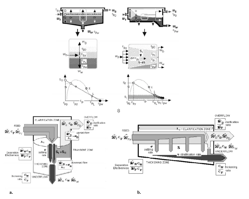
As is known, in continuous operations and once the system concerned (the solid-fluid suspension) has just been defined and the phenomenon under study has already been characterized (separation of macrofluids by sedimentation), the core of the sizing (or design) equation is a differential balance of the concerned property (mass of particulate solids), formulated in a representative volume differential element. That is to say: both the shape and the spatial (affected volume or surface) or temporal (residence time) extension of the enclosure (settler) where the phenomenon has taken place (analysis) or should have taken place (design) in a full-scale operation are adequately described (Figure 2).
The balance must consist of two members, one macroscopically descriptive (through an indicator property: mass concentration) of the differential change that takes place through this element, and the other (mass flux density) mechanistically descriptive of the kinetics of the process (massive gravitational sedimentation) and phenomenologically linked to the aforementioned space/time extension required for transit (obviously the horizontal surface area A [L2], normal to the driving force field, gravity):
and, consequently
W [L3t-1] being a coherent reference flow assumed as constant.
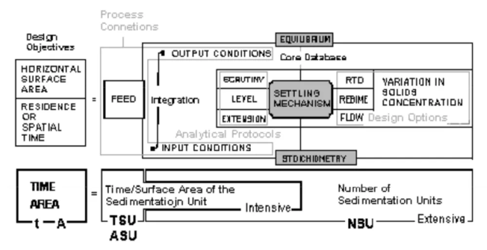
Equation (3) is the basic form of the so-called design equation for establishing the correspondence between objectives to be achieved and the space-time dimension of the equipment under the given operating conditions. The mode and difficulty of the integration of this type of equations (more precisely, intrinsic dimensioning equations, prior to the whole constructive and operational design) depend on two main determining factors: First, the form of the objective differential function according to the mode of operation, contact, flow, Residence Time Distribution (RTD) and regime of operation (all these boundary conditions modulate/conform the integration and can lead to important differences in the result). Second, its availability under an analytical or numerical formulation, as Figure 3 summarizes.Although the functions corresponding to the transport and transformation phenomena in stationary and transient regimes are formulated at the microscopic and molecular level of description, the mathematical analogy between this reference model and the one proposed in the aforementioned article [1] to describe the induced and macroscopically perceptible displacement in particles or macrofluid fragments due to selective force fields is evident.
This allows the transposition of theoretical concepts such as time of the sedimentation unit, TSU, the surface area of the sedimentation unit, ASU, and a number of sedimentation units, NSU, formulatable in a most theoretically complete analogous form in the particular, but the frequent case, that the kinetic term of sedimentation in Equation 1 could also be expressed analytically (by phenomenological deduction or by numerical induction) as a potential function of an adequate concentration descriptor (as occurs in mass transfer or chemical reaction).
In fact, there are models on the dependence of the sedimentation rate under dimensional and dimensionless forms of concentration such as its void fraction or porosity (e..g., as proposed by Richardson and Zaki [24], expanded through contributions by Keinath [6] and Laquidara [7] and others, and comparatively analyzed by Lavín [25]. This allows us to give full analogical meaning to the concepts TSU, ASU, and NSU (time, area, and number of sedimentation units) in a general formula that can be integrated or simplified according to the peculiarities of each flow and operation model in practice, discontinuous, BS (Batch Settler) or continuous, PFS and CSTS (Plug Flow and Continuous Stratified/Stabilized Tank Settler).
For a discontinuous device BS (Batch Sedimentation):
For a plug flow normal to the particle displacement device PFS (Plug Flow Sedimentation):
And for a vertical sedimentation device CSTS (Continuous Stratified/Stabilized Sedimentation):
This unitary procedure involves two contributions to the modelling of sedimentation. First, the generalization of unit operations methodology. Second, applying the analogy to two models of settler hydrodynamics: ideal vertical flow, (CSTS) and ideal horizontal progressive flow (PFS). That is a step in standardizing the elementary design (sizing: As) of settler-thickener through a generalized procedure open to any casuistic consideration of combinations and deviations of the basic models as Figure 3 attempts to synthesize.
On this basis, a generalization of the design equation model has been formulated. Also, a discussion about the concentration profile description protocols and their evolution is included in Section 4.2. This versatility evidences the logical limitations of the here-called “classical methods” (e.g. Coe and Clevenger [3], Yoshioka [5], etc), as what they really are: useful particular restricted forms of design only applicable to the CSTS flow conditions.
In fact, and as happens with any geometric dimension that is neither the transfer surface nor the homogeneous reaction volume, in the case of sedimentation the depth of the tank z has no direct effect on the segregation efficiency, being a simple consequence of the previous hydrodynamic design that allows the suspension to be configured according to the assumptions of the model, for instance, uniform horizontal flow, or vertical and uniform vertical or upward flow after division of flow and subsequent stabilization of currents and sediment fronts. Depth also plays a significant role in order to minimize particle entrainment as a consequence of agitation as well as that due to inlet, outlet, and/or particle drainage currents) Justifying this criterion and assuming the existence of an experimental optimum amplitude [26], it could be said that the extension of the phases in the direction of the sedimentation flow plays a retardant role similar to that of the thickness of the boundary layers in molecular transport.
In the same way, the expanded surfaces (lamellae) perform the same role of increasing effectiveness in sedimentation equipment as the surface area/volume ratio increasing resources or devices perform in heat and mass transfer unit operations or heterogeneous chemical reactors in momentum, mass, or heat transfer operations. In fact, the possibility of expanding the surface of transfer by dispersion or by creating interfaces through the presence of inert materials has an analogy in sedimentation, where the division of flow and the use of enlarged surfaces allow the increase of the surface area of tank volume, resulting in more compact designs [27].
Materials and methods
Materials
Suspended materials were employed to carry out batch sedimentation experiments in order to validate [28] our method [29,30]. Hard coal suspensions with concentrations of 10, 20, 50, and 100 kg.m-3, particle size under 500 μm with average size of 150 μm were used. In this case, the sedimentation was activated by flocculation by means of N-9-UD-120, a selected strong anionic polyelectrolyte made by Nalco, at a jar-test optimized dose level of 20 ppm.
Equipment
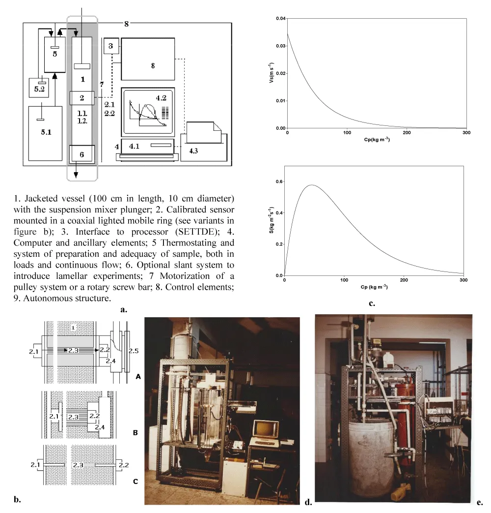
The raw data were obtained by means of an improved prototype of a photosensitive dynamic sedimentograph integrated by the different basic elements indicated in Figure 4.
Results and discussion: A comparative analysis
The authors wish to emphasize that neither the materials and operating conditions chosen -which, for that matter, could have been different- nor the numerical results obtained for them, have further interest than to serve as a test bank to contrast the calculation protocols analyzed here.
Application of the classical design methods
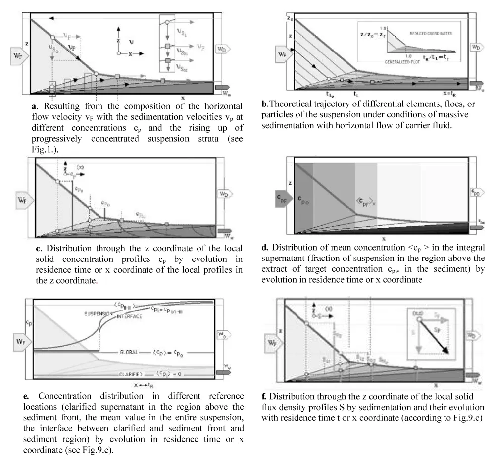
Of all the methods described in the literature, many of them analyzed by the authors at the beginning of this line of research, are summarized in the following paragraphs. Note that all these methods are only applicable to the flow model identified in this work as CSTS, whose macroscopic hydrodynamic and compositional characteristics are summarised in Figure 5a.
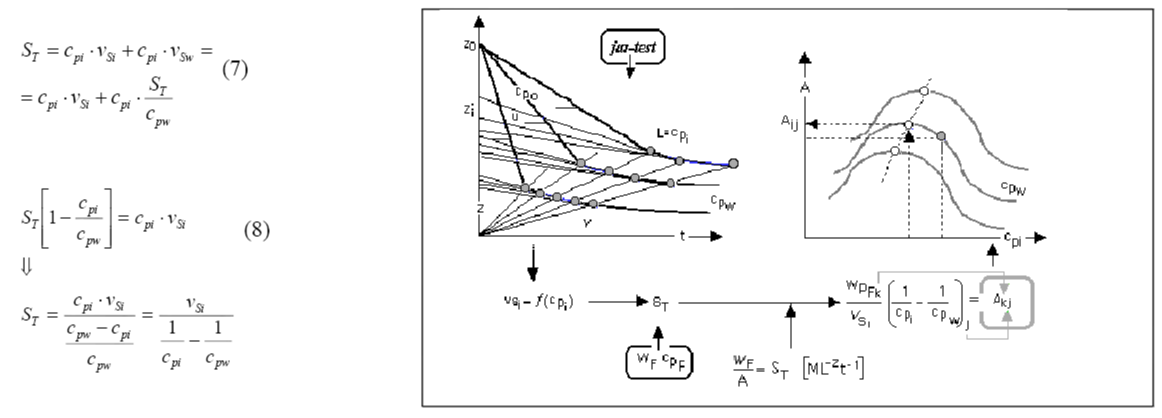
About the method of Coe and Clevenger: Coe and Clevenger's method [3] (1916) -that sufficiently withstands the passing of time-, mathematically interpreted by Kynch in the early Fifties, calculates the area needed for sedimentation on the assumption that all suspended solids will have the opportunity to be removed as concentrated sludge at cpw., equation (8). So, this expression is known as the CC formula, where the load to be treated, S, and the concentration conditions to be reached in the sludge, cpw are pre-established as connection variables according to information flow logical paths (Figure 2c), suffers from the basic shortcomings of these models: not to consider inertial effects, phase sedimentation and eventual compressibility of sediments. The degree of concentration set as a target in each case determines the corresponding value of that area. The balances proposed by the original work of these authors are complemented in Figure 6 with the operational help provided by other convergent models, as shown later in Figure 7.
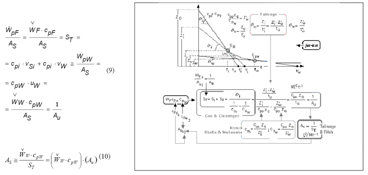
This method [4] is based on the direct graphical interpretation of a single kinetic curve according to the primary approach of the Kynch [17] model later endorsed by the contributions with which Shanon and Tory [39] and Michaels and Bolger [40]. Simultaneously, here the analysis of the evolution of solids concentration profile has been completed as a result of the interaction between the profile front (“first-order discontinuity” [17] between suspension and clarified supernatant) and the strata of progressive concentration (“second-order discontinuities” [17] introducing the concept of unit area Au, in (9) (Figure 7).
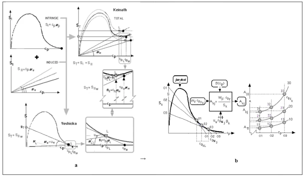
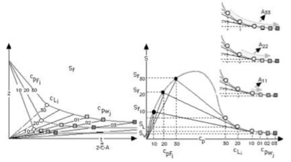
About the methods of Keinath and Yoshioka: As was established analytically in equation (7), adding the induced term of flow density by dragging for each hypothetical speed of discharge of sludge vw, SII, (Figure 4c) several plots of total flow ST (Figure 8) are obtained, that allow the characterization of bottleneck flow density through the settler and, thus, a maximum possible cpwconcentration. The higher the concentrated sludge, the lower the underflow rate (the slope of the SII(cp) line, also in Figure 8), the lower the limit concentration and the greater the required area As [Equation (6) from (7)]. Lakidara-Keinath's method [5, 6, and 7] makes it possible to only construct the sludge state curve (Figure 4c) and, from it, to test the values of the concentration at which a sludge of a certain preset /k initial concentration would be stabilised by the propagation of the fastest discontinuity depending on each evacuation velocity imposed on the settler. Yoshioka's method simplifies these attempts by introducing the simple graphical method that is transcribed and justified in Figure 8.a. Each preset /j value for the sludge would be stabilized in equilibrium with a static cpi concentration for a given underflow velocity and its corresponding capacity to carry solids to that concentration.
Application of the generalized design method
As introduced and justified in Section 2.2., equations. (2) to (6), and Figs. 2 and 3, this procedure [1] can be applied in different operation and flow configurations and is not restricted only to the casuistic and simple conditions of vertical stratified flow (CSTS) as these classical methods previously described in section 4.1. For this reason, regardless of the suitability of each hydrodynamic configuration - and its respective variants, either due to deviations from the basic models, due to regime peculiarities, or due to operation and design innovations appropriate to each particular problem - it seems to us more opportune to first develop its application to the most general case, illustrated by the PFS model, and subsequently introduce the drastic calculation simplifications applicable to the CSTS model.
In all cases, the procedure is strongly dependent on the way in which the characteristic data of the suspension to be treated are available. If an empirical or theoretical mathematical model of the kinetics and equilibrium (flux density of solids Sp) is available, as said before the method can be applied to its full extent.
Batch and progressive horizontal flow settler: In the horizontal flow (PFS), see Figure 5b, the discontinuous sedimentation pattern is reproduced, giving rise to a correspondence between the time (elapsed time) and the space traversed by flowing suspension in that time (notice that residence time, or spatial time, are conceptual synonyms only in phenomena whose evolution does not imply substantial global volumetric changes, just as frequently occurs in solid-liquid sedimentation phenomena).
Due to this space-time equivalence, the same RTD pattern of profiles of distribution takes place in discontinuous or batch operation [28]. Thus, the objective design parameter for a discontinuous settler, BS, in process mode is usually the horizontal surface area to achieve adequate concentration. This is achieved through the sedimentation of a suspension volume of pre-established concentration in a pre-established operation time. However, the usual procedure- in analytical mode (jar-tests, Figure 9)- is to operate with a settler (frequently cylindrical in shape) with a pre-established section, and linking the operating time (tBS) to the volume Vs (indirectly, to the initial suspension level). The design equation under this configuration is the one already shown in Equation 4.
In the case of a plug flow (normal to the particle displacement) device PFS, this analogue model -as occurs in its application to other basic operations- does not condition the morphology of this surface, which in the case of horizontal flow settlers is associated by default to the rectangular prismatic geometry (APFS= Axy) as a single bottom container, or distributed in lamellae, the most frequent way (Rodríguez P, et al. [9]) to enlarge the effective surface of the equipment minimizing the volume. The horizontal surface area of the settler is that written in Equation 5. The depth z of the tank resulting from this morphological convention - consistent but optional- is a secondary parameter to be established discretionally by elemental hydrodynamic considerations, fundamentally with the collateral objective of maintaining a laminar flow regime (potential flow in the PF ideal model) below the sediment (Figures 9a,b), which for a pre-established feed flow rate WF depends on the Azy surface.
In both cases, the simplifications due to the lack of a mathematical kinetic formulation have been resolved by introducing in equations [4] and [5] an average form of flow density of settling solids, < S p >t, which, in the case of the PFS, would be identical to a spatial mean. Note that, even though - as is known - Sp is a function of cp, the recently emphasized space-time analogy and the manifest local discontinuity that concentration presents (Figures 9c,e and f) suggest that, in this case, the greater physical sense and phenomenological coherence that all averaging requires are achieved by using as a reference coordinate continuous variables that are a link between the substantial variables S and cp. Such is the case of time t, position x, or any other functional indicator of the global progress of the process, e.g. the mean concentration
Expanding on the collateral analogies, in this case between the PFS design and the CSTS, a collateral-specific area could be redefined here as
That can be assimilated into the previously mentioned concept of unit area introduced by Talmadge and Fitch (1955) in the design of CSTS.
Vertical flow settler: For a vertical sedimentation device CSTS the surface requirements have already been presented in Equation (6).
As is known, the stationary stoichiometry of this ideal model of stratified flow is very simple, and the design equation is based on the partial global balance of matter (Equation 9), being vw the imposed underflow rate, and accepting that the slurry, in the objective conditions cpw - whether or not this being the one with the maximum compaction- does not represent a computable intrinsic and additive contribution to sedimentation once leaving the enclosure as indicated in Figure 8a. The resolution of the balance, together with the auxiliary equations for the definition of sedimentation velocity vsi and strata propagation rate usi= vw, from information previously available, as kinetic v(cp) or state S(cp) data or mathematical formulations, can be done analytically, numerically or graphically by trial and error. This problem, without analogical pretensions and directly oriented to the calculation of the area, was already solved imaginatively by Yoshioka.
Comparative results
CSTS: Table 1 summarises the values of the sedimentation surface areas predicted by the three classical models for a simple casuistical set ij of 4(in) x 4(out) conditions preceded by those obtained by applying the generalised approach according to Equation 6, which, in the illustrative example chosen, allowed the separate calculation of the values of ASU and the NSU. It can be observed, as could not be otherwise since it is calculated with the same theoretical and practical assumptions, that the values are concordant in a narrow band with differences less than 2% in most cases. The Talmadge and Fitch method is the most discrepant for the concentrations of 250 and 300 kgm-3 showing departures up to 20%. This is due to the fact that -for greater procedural realism- the errors derived from a rudimentary graphic calculation are notorious.
PFS: As said in Section 4.2., the so-called classical methods are not compatible or applicable with this flow condition (formulated only for the vertical flow settler, with stratified concentration, as said before, here called CSTS, by analogy with the CSTR model. Thus, Table 2 summarises the values of the sedimentation surface areas predicted by the proposed generalised model (equation 5) as well as the values of ASU and the NSU for a simple set ij of 3 x 4 conditions (Figure 10).
Conclusion
Also circumscribing different stages, our research has included artisanal sedimentation by loads, continuous sedimentation in pilot plants, the design of analysis equipment, hydrodynamic interpretation, and, finally, the configuration of a unitary sedimentation model, transposing to this field all the possible resources among those widely developed to macroscopically characterize the energy and matter transfer and reaction operations as a result of the integration of molecular transport and transformation phenomena.
- In fact, while in conventional operations the macroscopic property flows -matter, amount of movement, and heat energy- are the result of the integration of microphenomena of diffusion and molecular transformation of these same properties, the convective and unidirectional flow of matter that occurs in sedimentation (as well as inertial separations, flotation, and filtration) is the indirect net macroscopic integral consequence/result of momentum flux in the interface of particulate SF systems (inertia vs. friction).The generalized methodology can be applied in its full analogical mathematical formulation (in order to differentially identify TUS, AUS, and NUS) to the sedimentation equipment design only if the settling velocity-concentration relationship and the flow model are numerically or analytically well defined.
- For the CSTS, it was necessary to obtain the settling velocity vs. concentration relationship in analytical or graphical form and do an iterative calculation of the underflow velocity. This approach leads to results similar to the Talmadge-Fitch method and is almost coincident with that obtained by the methods of Coe-Clevenger and Keinath-Yoshioka.
- For the PFS, the mass flow density (settling velocity times concentration) was time-averaged between the initial (feed) condition and the final (thickened sludge) one. This allows us to obtain the area of the sedimentation unit. The results agree reasonably well with the expected results for this flow model directly obtained from jar-test experiments.
- Although the surface requirements are generally lower in PFS settlers, the operational and control requirements are more complex with this configuration, particularly due to disturbances caused by interfacial drag and the greater difficulty of sediment transport.
- It is reiterated that neither the particular data used here nor the connection or objective conditions have in themselves any other particular interest than serving as a casuistical exemplification of the proposed method. That said, the surface requirements of one and another flow configuration are very dependent on the feeding conditions and those required in the thickening due to the particular sedimentability characteristics (state curve) of each suspension.
About the perspectives
The state of the art in settling research highlights some recurrent peculiarities. If settling modelling owes its origin to a mathematician (Kynch), the current situation depicts the field of sedimentation with a progressive withdrawal of experimental works and as a testing ground for the most sophisticated flow simulation models by methods that range from the simple unidimensional models to 3D grids studied in both Eulerian and Lagrangian coordinates. Some standardized technologies, such as Particle Tracking Velocimetry (PTV) or simulation Computational Fluid Dynamics (CFD) software, help to understand many phenomena whose insufficient description comes from long ago, to dimension appropriate feed and discharge systems and to justify not only the procedure described here but also many others derived from the extension of the S(cp) model to complex situations.
The proposed generalist method allows us to take a step further in the analysis of real sediments and in the sizing of sediments in which a deviation from the ideal models proposed here is unavoidable or foreseen, which is inaccessible to the casuistical methods also critically analyzed here. Such is the case not only of deviations from the geometry and ideal flow conditions but also of modifications in the semi-continuous operation regime, more complex configurations, such as pulsating or recirculating settlers with recirculation, transitory states, overfeeding, underfeeding and fractional separation and mixed or multi-stage separation treatment systems in fractionation mode.
This article is particularly indebted to Spanish funding entities, March Foundation, Comisión Asesora de Investigación Científica y Técnica (CAICYT), Comisión Interministerial de Ciencia y Tecnología (CICYT), Fundación en Asturias para el Fomento de la Investigación Científica y Técnica (FICYT). To the initiator of the line of research, Prof. José Coca (1973), and to those who, throughout decades of work - either within their Doctoral or Bachelor Thesis or in the context of successive projects and contracts not expressly referred to here -contributed to the configuration of a database and to the development of pilot plants and different prototypes of analytical and process equipment prior to the devices here described: Ángel Cagigas, José González-Cañibano, Enrique Cuesta, Julio-David Fernández, Juan Folgueras, Rufino García, Mª.Camino Gutiérrez, Valentín.Díaz-Junquera(+), Julio Lorenzana, Enrique Mier, Marisol Muñiz, Patricia Rodríguez, Pedro Santamaría and Guillermo Velasco. The authors give special recognition to the more recent and invaluable advice of Prof. J.Ángel Rodríguez on the discussion and mathematical foundation, homologation, and resolution of the proposed models.
Conflict of interest statement
There is no reason for a conflict of interest either with financial institutions for projects supported by public calls, or with companies for which - also at the time - specific concerted studies were carried out, or with collaborators or consultants who, except involuntary omission, are cited here with our well-deserved recognition.
Subscripts and superscripts
/B Referring to RTD conditions in Batch operation: e.g. Sedimentation BS
/CST Referring to RTD conditions in Continuous Stirred Tank Operation: e.g. Sedimentation CSTS
/PF Referring to RTD conditions in Continuous Plug Flow Operation: e.g. Sedimentation PFS
/D Referring to overflow conditions
/FReferring to feed conditions
/i, Referring to local conditions or significant points in the characteristic graphical representations
/kj Referring to the operating conditions when certain values of connection variables k correspond to others j of objective properties
/I,II Referring to differentiated streams, phases, or flow regions
/L Referring to discontinuity conditions
/m Referring to compaction conditions
/o Referring to initial conditions
/P Referring to particles, when necessary to make it explicit
/x,y,z,t Referring to particular space-time conditions
/w Referring to underflow conditions- Bueno JL, Lavín AG, Mahamud MM, Muñiz M, Rodríguez P. Recent Innovations in Chem.Eng. 2019; 12:15-53.
- Chilton TH, Colburn AP. Distillation and Absorption in Packed Columns A Convenient Design and Correlation Method. Ind.Eng.Chem. 1935; 27: 255.
- Coe H, Clevenger GH. Transactions. Of the American Inst. of Mining Eng. 1916; 55:356-384.
- Talmadge WP, Fitch EB. Determining thickener unit areas. Ind. and Eng. Chem. 1955; 47:38-41.
- Yoshioka N, Hotta Y, Tanaka S, Naito S, Tongami S. Chemical Engineering, Tokyo. 1957; 21:66-74.
- Keinath TM. Activated sludge-unified system design and operation. J.Environ. Eng. Div. 1977; 103(5):829-849.
- Laquidara VD, Keinath TM. Mechanism of Clarification Failure. J.Water Poll.Contr.Fed., 1983; 55:1; 54-57.
- Le Goff P.« Rustique Génie Chimique » in Technologie des solides divisés. Stages de Formation des Ingenieurs. ENSIC-CPIC, Nancy. France. 1991.
- Brown GG, Katz D, Foust A, Schneidewind R. Unit Operations, J. Wiley&Sons. 1955.
- Degrémont .Technical handbook on water. 1979; ISBN 84-300-1651-1.
- Bueno-Martínez G. Sciences as Categorical Closures. Pentalfa. 2013; ISBN 9788478485437.
- Bueno JL, Lavín AG, Coca J. Ing. Quim. 1986; 208:159-175; 210:131-139 and 213, 65-77.
- Concha F, Bürger R. Thickening in the 20th century: a historical perspective. Minerals & Metallurgical Process. 2003; 20:2; 57-67.
- Concha F. Solid-liquid separation in the Mining Industry, Springer Verlag. 2013; ISBN 978-3-319-02483-7.
- Garrido F, Concha F, Bürger R. Int. J. Mineral Process. 2005; 72, 57-74.
- Sangkyum K. J.Ind. Eng.Chem. 2009;15, 45-49.
- Kynch GJ. A theory of sedimentation. Trans Faraday Soc. 1952; 48:166-176.
- Fitch B. Ind.Eng. Chem. 1966; I58:10; 18 289.
- Fitch B. AIChE J. 1983; 29:6; 940-947.
- Tiller FM. Revision of Kynch sedimentation theory. AIChE. 1981; 27:5; 823-829.
- Obata E. Watanabe, Analysis of semi-continuous thickener using a batch settling curve, H. Journal of Chem. Eng. of Japan. 1979; 12(4):307-312.
- Michaels AS, Bolger JC. Settling rates and sediment volumes of flocculated kaolin suspensions. I&EC Fundamentals. 1962; 1:24-33.
- Bargiel M, Tory EM. Extension of the Richardson–Zaki equation to suspensions of multisized irregular particles. Int.J. Mineral Processing. 2013; 120:22-15.
- Richardson JF, Zaki WN. Trans. of the Inst. of Chem. Eng. 1954; 32:35-53.
- Lavín AG, Mahamud MM, Rodríguez P, Bueno JL. Recent Patents on Chem. Eng. 2010; 3:129-141
- Rodríguez P, Lavín AG, Mahamud MM, Bueno JL. Chem. Eng. & Processing: Process Intensification. 2008; 47(9-10):1705-1706.
- Lavín AG, Bueno JL. Quím. e Ind. 2002; nº527; 49:2; 94-111.
- Font R. Analysis of the batch sedimentation test. Chem.Eng. Sci. 1991; 46:10; 2473-2482.
- Bueno JL. Lorenzana JJ, García R. An empirical model of the efficiency of commercial polyelectrolyteson secondary settlers design. J. Powder Technology Eng. 1993; 75:119-125.
- Bueno JL, Coca J, Cuesta E, Lavín AG, Velasco G. Sedimentation of coal slurries: a procedure for the determination of the flocculated-solid flux curve useful for the design of continuous settling tanks. Powder Technol. 1990; 63:133-140.
- Hunosa & UniOvi [Coca J, Bueno JL, Lavín AG, Cañibano JG, García R, Gutiérrez MªC, E Mier, G.Velasco] 1988,. Digital analogical photosensitive sedimentograph SEDIGRAPH® (Spanish Patent 8800257).
- Bueno,JL, Coca J, Cañíbano JG. 1st Mediterranean Congress on Chem. Eng. Proceedings. 1978; 1:756.
- Bueno JL, Gutiérrez MªC. 4th Mediterranean Congress on Chemical Engineering. 1. Advances in the analysis and synthesis of Chemical Processes. 1987; 1:1.3.44: 366-367.
- García R, Bueno JL, Lavin AG. Gutiérrez MªC. CATS 90. Int. Conference. 1990; 293-295.
- Lavín AG. A Contribution to the study of settlers: Pilot plant for flocculation, clarification and thickening of coal mining waste water. Ph.D. Thesis. University of Oviedo. 1984.
- Bueno JL, Gutiérrez MªC, Mier E, Bayón A, Viejo BR, Cano F. 4th Mediterranean Congress on Chem. Eng. Advanced Technologies. 1987; Vol. II, 3:3.4.14, 768-769.
- Muñiz M, Berthiaux H, Lavín AG, Bueno JL. Pilot-plant studies of non-steady-state continuous sedimentation: hydrodynamics and solids distribution profiles. 1998, Powder Technology 96; 267 -274
- Berthiaux H, Bueno JL, Lavín AG, Muñiz M. Hydrodynamic model for the separation of the flows in a pilot plant equipment. Canadian J. of Chem. Eng. 2007; 85:2; 158-170.
- Shanon PT. Tory EM. Settling of slurries—new light on an old operation. Ind.Eng.Chem. 1965; 57:2; 18-25.
- Michaels AS, Bolger JC. Settling rates and sediment volumes of flocculated kaolin suspensions. I&EC Fundamentals. 1962; 1:24-33.
Article Alerts
Subscribe to our articles alerts and stay tuned.
 This work is licensed under a Creative Commons Attribution 4.0 International License.



 Save to Mendeley
